• Do not touch the ends of connectors. Touching the ends can leave fingerprints and cause other
contamination.
• Inspect routinely for dust and damage. If you suspect damage, clean and then inspect fiber ends under a
microscope to determine if damage has occurred.
Interfaces and Port Description
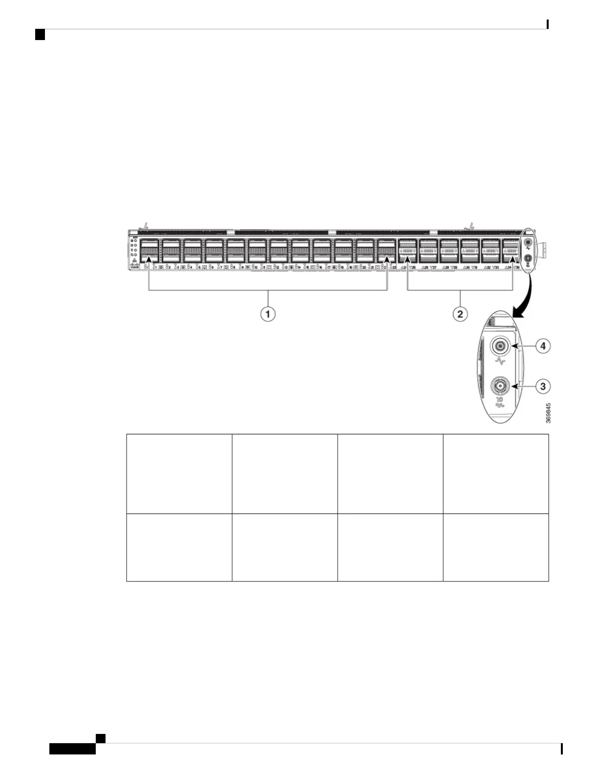
Figure 12: Cisco 8201 Fixed Port Router - Front View
Mini coax connector for
10MHz, input, and output.
3400G Ports (Port 0 to Port
23). 400G port supports
40GE, 100GE, 200GE,
and 400GE. All 400G port
support breakout
operation.
1
Mini coax connector for 1
PPS, input, and output.
4100G ports (Port 24 to
Port 35) support 100G and
40G. Ports 24, 26, 28, 30,
32, and 34 support 4x10G
via breakout cable.
2
Hardware Installation Guide for Cisco 8200 Series Routers
26
Connect Router to the Network
Interfaces and Port Description