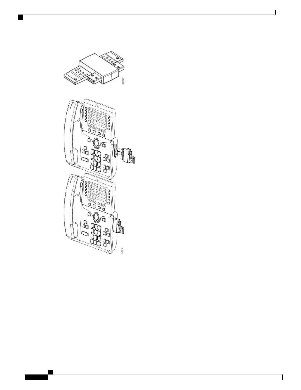
This diagram shows the spine connector.
This diagram shows the installation of the spine connector.
Step 7 Connect the other end of the spine connector to the key expansion module as shown in this diagram.
a) Align the spine connector with the key expansion module accessory connector ports.
b) Firmly press the key expansion module into the spine connector.
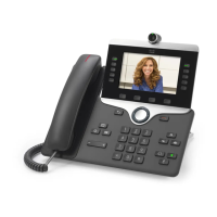
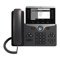
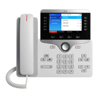
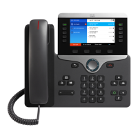
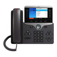
Cisco IP Phone Accessories
18
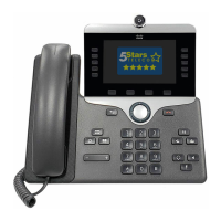
Cisco IP Phone Accessories
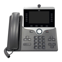
Cisco IP Phone Accessories