EasyManuals Logo

Cisco 890 Series User Manual

Cisco 890 Series
292 pages
To Next Page IconTo Next Page
To Previous Page IconTo Previous Page
Page #156 background imageLoading...
Page #156 background image
2-4
Cisco Integrated Services Router Hardware Installation Guide
Chapter 2 Installing the Router
Installing the Cisco 810 ISR
Figure 2-2 6-32 Screws
Step 3 Connect the supplied plenum rated Cat5 cable to the GE0 port on the PoE+ splitter.
Step 4 Connect the Cat5 cable from your PoE+ source to the PoE+ in port on the PoE+ splitter.
Step 5 Place the power cord lock onto the power cord behind the connector overmold as shown in Figure 2-3.
Slide the power cord lock forward so that it captures the overmold and is fully seated.
Figure 2-3 Placement of the Power Cord Lock onto the Power Cord
285668
1
2
3
4
1 6-32 screws 3 To PoE+ power source
2 Power cable with power cord lock installed 4 GE CAT5 cable
345076
1
2
1 Power cord connector
2 Power cord lock

Table of Contents

Other manuals for Cisco 890 Series

Questions and Answers:

Question and Answer IconNeed help?

Do you have a question about the Cisco 890 Series and is the answer not in the manual?
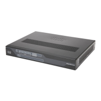
Cisco 890 Series Specifications

General IconGeneral
Product TypeRouter
Form FactorDesktop
USB Ports1 x USB 2.0
FirewallYes
VPN SupportYes
RAM256 MB
Wireless802.11n
Operating Temperature32°F to 104°F (0°C to 40°C)
Operating Humidity10 to 85% non-condensing
Connectivity TechnologyWired
Data Link ProtocolEthernet, Fast Ethernet, Gigabit Ethernet
Network / Transport ProtocolTCP/IP
Routing ProtocolOSPF, BGP, RIP-1, RIP-2, EIGRP, HSRP, VRRP
Remote Management ProtocolSNMP, Telnet, HTTP, HTTPS, SSH
FeaturesVPN support, firewall protection, Quality of Service (QoS), VLAN support
Encryption AlgorithmAES, 3DES, DES

Related product manuals