10
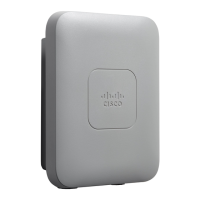
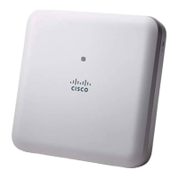
Figure 2 Face of the 2802E Model
The ports and connections on the bottom of the access point are shown in Figure 3.
1
Dual-band antenna connector A
5
Status LED
2
Dual-band antenna connector B
6
Location of the ports and connectors on the
head of the AP
3
Dual-band antenna connector C
7
Location of the Smart antenna connector
port on the right side of the AP
4
Dual-band antenna connector D