To replace or upgrade the Cisco ASR1000-RP1 DIMM memory spare, follow these steps:
SUMMARY STEPS
1. Attach an ESD-preventive wrist strap between you and an unpainted router surface.
2. Locate the DIMM on the system board.
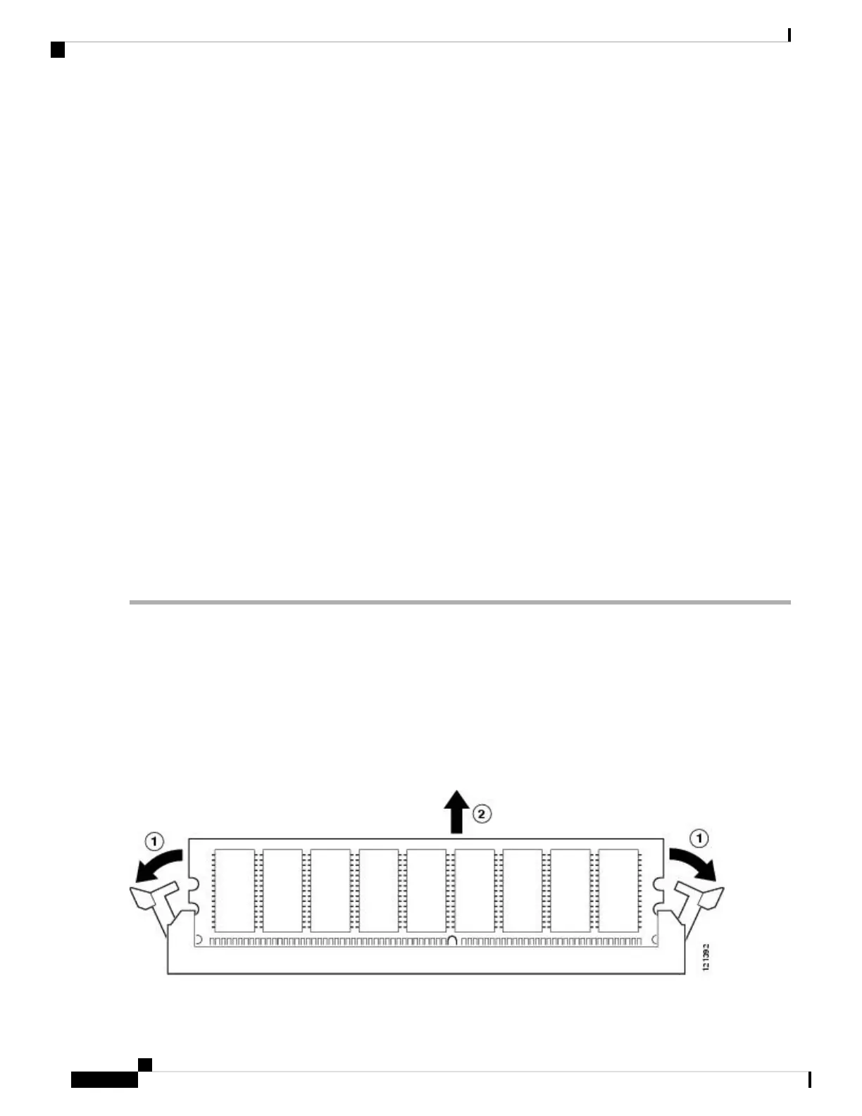
3. Press both spring latches outward to release the DIMM.
4. Pull the latches away from the DIMM on both edges. This lifts the DIMM slightly. Gently lift the DIMM
free from the DIMM connector, taking care not to touch the pins that insert into the socket.
5. Place the DIMM in an antistatic bag to protect the DIMM from ESD damage.
6. To install the DIMM memory card, locate the notches and align the DIMM with the socket before
inserting it.
7. Make certain that both latches on the DIMM connector are open.
8. Gently insert the new DIMM, taking care not to damage the pins on the edge of the DIMM.Using two
hands, place the index fingers on the edge of the DIMM and place the thumbs on the socket, being
careful not to touch the socket pins. Press on the back of the DIMM towards the socket by squeezing
the index fingers and the thumbs together, being careful to only apply force onto the DIMM parallel
with the plane of the DIMM.
9. To allow the DIMM to slide into the socket smoothly with minimum force, one can alternate applying
force back and forth between the left hand and the right hand, allowing one side to engage prior to the
other. Carefully and firmly press the DIMM into the connector until the spring latches lock the DIMM
in place. See Figure 14-12.
10. Slide the DIMM one side at a time. Use light insertion force and insert smoothly; but make certain the
DIMM is inserted straight .
DETAILED STEPS
Step 1 Attach an ESD-preventive wrist strap between you and an unpainted router surface.
Step 2 Locate the DIMM on the system board.
The DIMMs shown in xref Figure 14-12 and Figure 14-13 are representative and might not look exactly like
the DIMMs used on the RP; but the procedure is the same.
Note
Step 3 Press both spring latches outward to release the DIMM.
The following figure shows the Cisco ASR 1000 Series RP DIMM module spring latches.
Figure 12: Cisco ASR 1000 Series RP DIMM Module Spring Latches
Removing and Replacing FRUs from the Cisco ASR 1000 Series Routers
22
Removing and Replacing FRUs from the Cisco ASR 1000 Series Routers
Removing and Replacing the Cisco ASR1000-RP1 DIMM Memory Modules
 Loading...


