• Remove the power supplies before you remove the chassis top cover.
The top cover cannot be removed until the power supplies are removed from the
chassis. The chassis has a safety mechanism built in to prevent the removal of
the top cover until the power supplies are removed.
Caution
Procedure
Step 1 With an ESD wrist strap on, remove the power supplies from the chassis.
The chassis cover cannot be removed until the power supplies are removed from the chassis.
Note
For instructions about how to remove the AC and DC power supplies, see:
• Removing AC Power Supplies
• Removing DC Input Power Supplies
Step 2 Remove the chassis top cover by performing the following steps:
a) Remove the fourteen top surface screws on the chassis cover.
b) Remove the two screws from the left side of the chassis and the two screws from the right side of the
chassis.
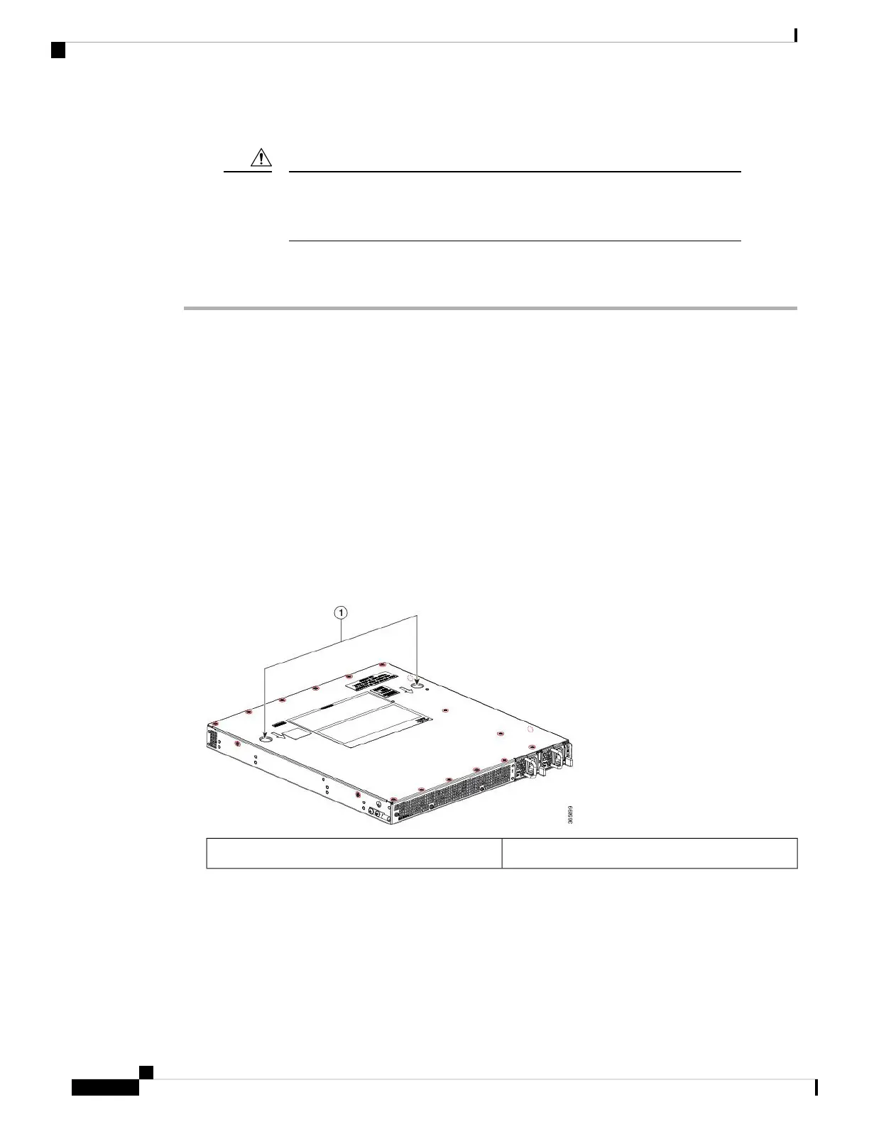
c) Putting your thumbs in the thumb depression shown in the following figure, slide the cover slightly
backward and lift it off of the chassis.
Figure 7: Cisco ASR 1001-HX Router Top Cover Screw Locations
Thumb depression location1
Step 3 Locate the DIMMs on the router.
The following figure shows the location of the DIMM slots in the Cisco ASR 1001-HX Router.
Removing and Replacing FRUs
10
Removing and Replacing FRUs
Removing a DIMM from a Cisco ASR 1001-HX Router

 Loading...


