Figure 6: DC Power Supply Terminal Block Ground Cable Lugs
This illustration shows the DC power supply for the Cisco ASR 1002-HX Router. The airflow for
the Cisco ASR 1002-HX Router is reverse of what is shown in this illustration.
Note
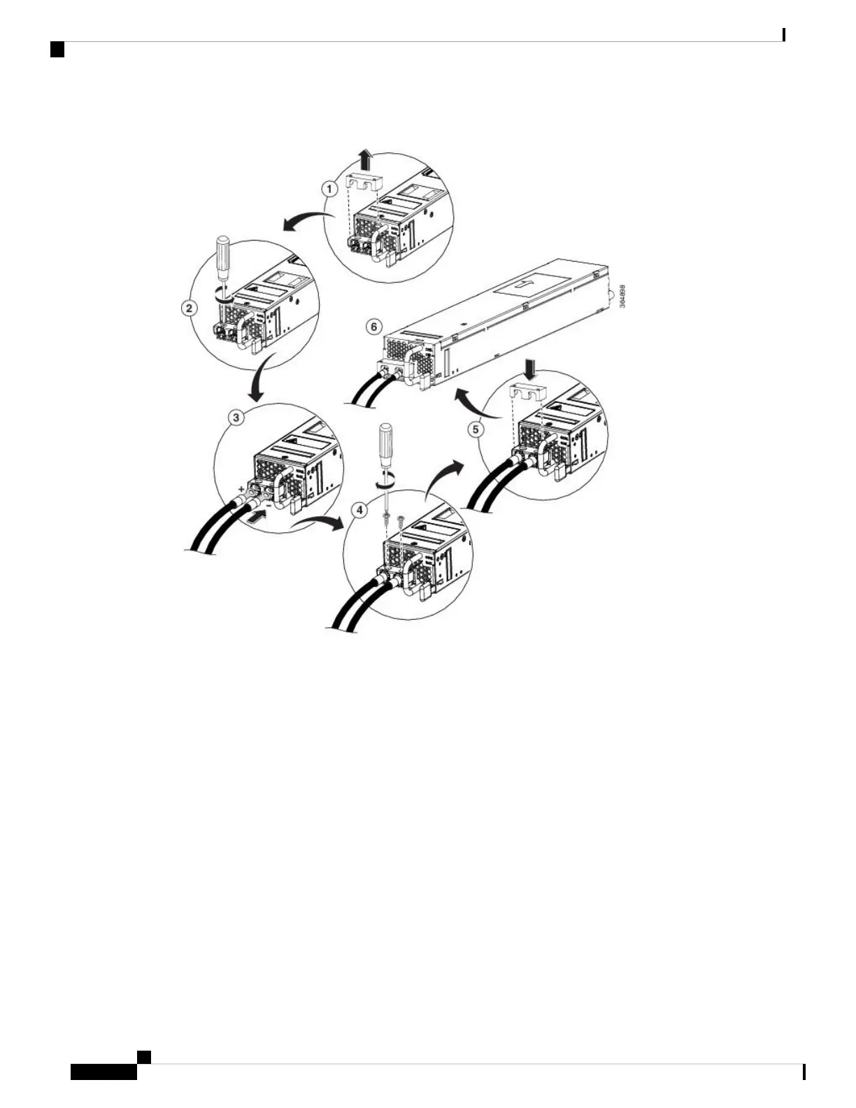
Step 5 For easier cable-management, insert the negative lead cable first. Replace the ground lug with cable in the
following order:
a) Wire terminal
b) Screw with captive washer
Step 6 Tighten the M3 Screw with captive washer to recommended torque of 5 in-lbs for the positive stud and wire.
Secure the wires coming in from the terminal block so that they cannot be disturbed by casual
contact.
Note
Step 7 Replace the terminal block plastic cover. The plastic cover is slotted and keyed to fit correctly over the terminal
block.
Step 8 Turn on the circuit breaker at the power source.
Step 9 If you have changed the chassis power switch to the Standby position in step 2, turn the power switch to the
On position.
Removing and Replacing FRUs
8
Removing and Replacing FRUs
Wiring the DC Input Power Source

 Loading...


