b) Ground lug with positive wire
c) Kepnut screw
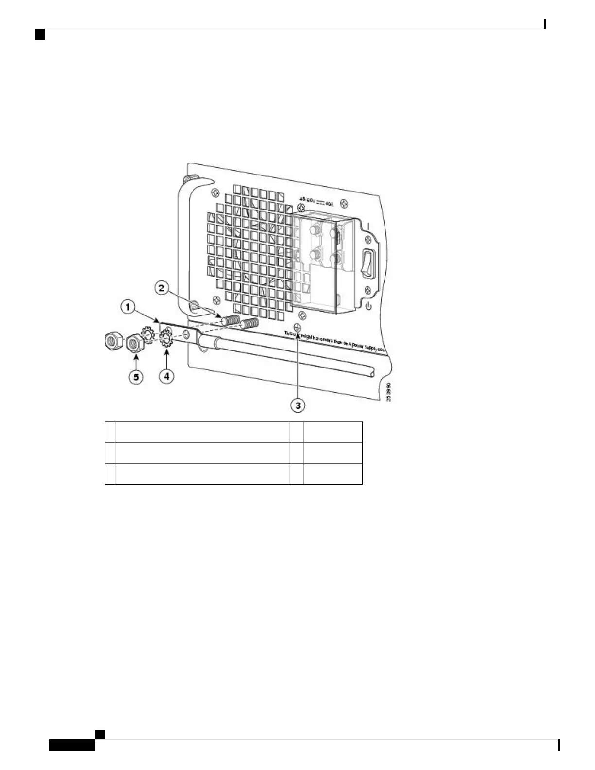
The following figure shows the DC power supply terminal block with the order of installing the screws and washers
on the ground lug.
Figure 71: Cisco ASR 1013 Router DC Power Supply Ground Lug Installation
Flat washer4DC power supply grounding stud with wire1
Kepnut screw5Grounding screws2
——DC power supply ground symbol3
Step 9 Tighten the Kepnut screw (use the screwdriver to tighten the ground screw in the terminal block to a torque of 20+/–2
in-lbs / 2 per.) and repeat the same steps for the negative wires.
Secure the wires coming in from the terminal block so that they cannot be disturbed by casual contact.
Note
Step 10 Use tie wraps to secure the wires, so that the wires are not pulled from the terminal block by casual contact. Ti-wrap
studs are located below the power supply terminal block.
The following figure shows the DC power supply terminal block with cables connected.
Removing and Replacing FRUs from the Cisco ASR 1000 Series Routers
106
Removing and Replacing FRUs from the Cisco ASR 1000 Series Routers
Replacing the DC Power Supply in Cisco ASR 1013 Router
 Loading...


