•
The color coding of the DC input power supply leads depends on the color coding of the DC power
source at your site. Typically, green or green/yellow is used for ground (GND), black is used for –48 V
on negative (–) terminal and red is used for RTN on the positive (+) terminal. Make certain the lead
color coding you choose for the DC input power supply matches lead color coding used at the DC power
source.
•
For DC input power cables, select the appropriate wire gauge based on the National Electrical Code
(NEC) and local codes for 40-amp service at nominal DC input voltage (–48/–60 VDC). Three pairs of
cable leads, source DC (–) and source DC return (+), are required for each power distribution unit (PDU).
These cables are available from any commercial cable vendor. All input power cables for the chassis
should have the same wire gauge and cable lengths should match within 10 percent of deviation.
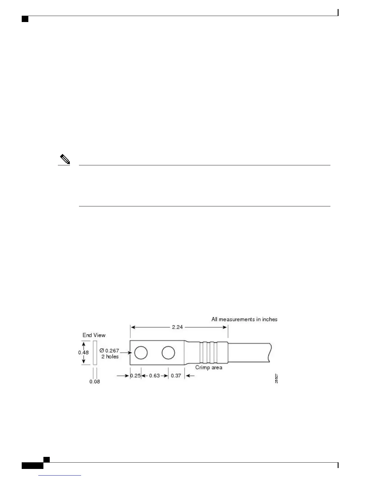
Each DC input power cable is terminated at the PDU by a cable lug. The cable lugs must be dual-hole, and
have a straight tongue. They must be able to fit over 1/4-inch terminal studs at 0.625-inch (15.88-mm) centers.
DC input power cables must be connected to the PDU terminal studs in the proper positive (+) and negative
(–) polarity. In some cases, the DC cable leads are labeled, which is a relatively safe indication of the
polarity. However, you must verify the polarity by measuring the voltage between the DC cable leads.
When making the measurement, the positive (+) lead and the negative (–) lead must always match the (+)
and (–) labels on the power distribution unit.
Note
•
A ground cable is required for each DC PDU. We recommend that you use at least 6-AWG multistrand
copper wire. This wire is not available from Cisco Systems; it is available from any commercial cable
vendor.
The ground wire cable lug should be dual-hole (as shown in Figure 15: DC Input Power Cable Lug, on page
34) and able to fit over M6 terminal studs at 0.625 inch (15.88mm) centers. Recommended lug terminal wire
size Panduit part number:
•
LCD8-14A-L for 8AWG wire size
◦
◦
LCD6-14A-L for 6AWG wire size
Figure 15: DC Input Power Cable Lug
Cisco ASR 1000 Series Router Hardware Installation Guide
34
Cisco ASR 1013 Router Overview and Installation
Connecting DC Input Power to Cisco ASR 1013 Router
 Loading...


