b) Tighten the Kepnut screws on the power supply studs.
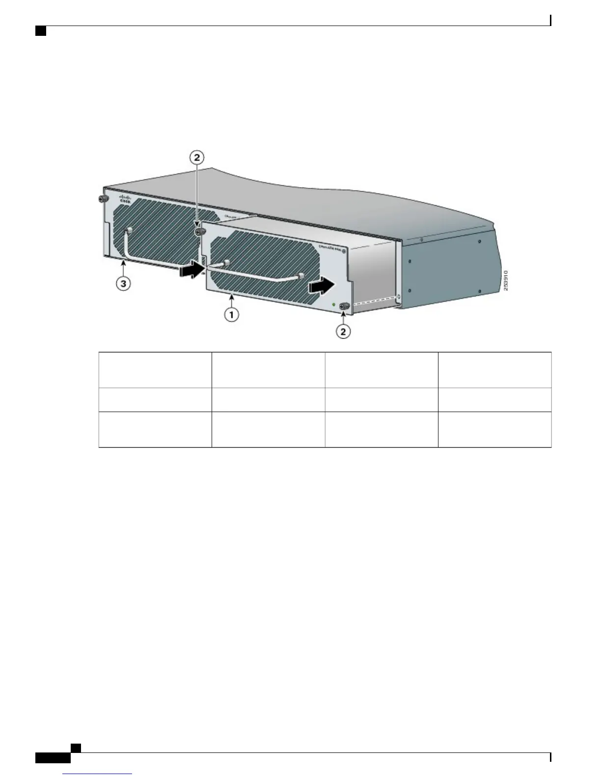
Figure 16: Cisco ASR 1013 Router DC Power Supply Grounding Stud and Cable
Flat washer4DC power supply
grounding stud with wire
1
Kepnut screw5Grounding screws2
——
DC Power supply ground
symbol
3
Shielded cables must be used to connect to the DB-25 alarm connector on both the AC and DC power
supplies in order to comply with FCC/EN55022/CISPR22 Class A emissions requirements. See the “How
Cisco ASR1000-RP Alarm Monitoring Works” section.
Note
Step 3
Attach the other end of the cable to the site’s ground connection.
Step 4
Remove the plastic cover from the terminal block.
Before you continue to install the terminal block ground wires, stop and perform Step 5. To prevent any
contact with metal lead on the ground wire and the plastic cover.
Caution
Cisco ASR 1000 Series Router Hardware Installation Guide
36
Cisco ASR 1013 Router Overview and Installation
Connecting DC Input Power to Cisco ASR 1013 Router
 Loading...


