12-24 screws for attaching
the baffles (four per side)
3Right side air baffle1
Left side air baffle2
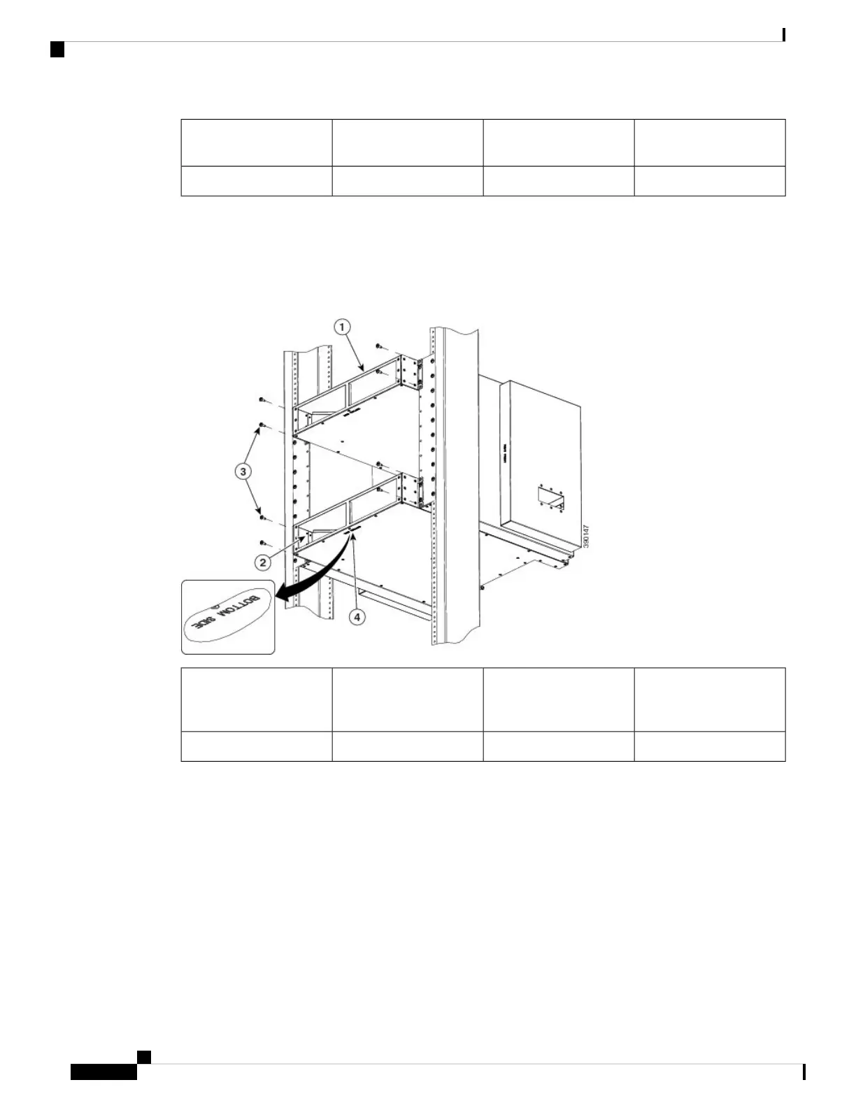
Step 3 Install the top and bottom air deflectors (Figure 88: Attaching the Air Deflectors on the Cisco ASR 9904
Router Chassis —Top View, on page 88) with the “bottom side” stamp facing down (note that the top and
bottom air deflectors both have the same part number: 800-41357-01).
Step 4 Tighten the screws to a torque of 41 in-lb.
Figure 88: Attaching the Air Deflectors on the Cisco ASR 9904 Router Chassis —Top View
12-24 screws for attaching
the air deflectors (two
screws per side)
3Top air deflector1
Bottom side stamp4Bottom air deflector2
Step 5 Secure the side air baffles to the air deflectors using the supplied 8-32 screws (Figure 89: Securing the Cisco
ASR 9904 Router Chassis Side Baffles to the Air Deflectors (Rear View), on page 89). Do not tighten the
screws.
Unpacking and Installing the Chassis
88
Unpacking and Installing the Chassis
Installing Optional Air Baffles on the Cisco ASR 9904 Router

 Loading...


