14
Install the Cables Using the Cable-Management Bracket
Cables coming off the front side of the Cisco ASR 1002-F integrated RP and SPAs utilize the chassis-level cable-management
brackets provided on the chassis rack-mount brackets (see Figure 11).
To secure SPA cables and input or output cables connected to the Cisco ASR 1002-F Router, follow these steps:
Step 1 When installing the network interface cables, route the cables up to and through the cable-management bracket ‘U’
device. If you are using very thin cables that slip through the bracket openings, insert nylon cable ties through the holes
in the bracket and wrap them around the cables to secure them as shown in Figure 11.
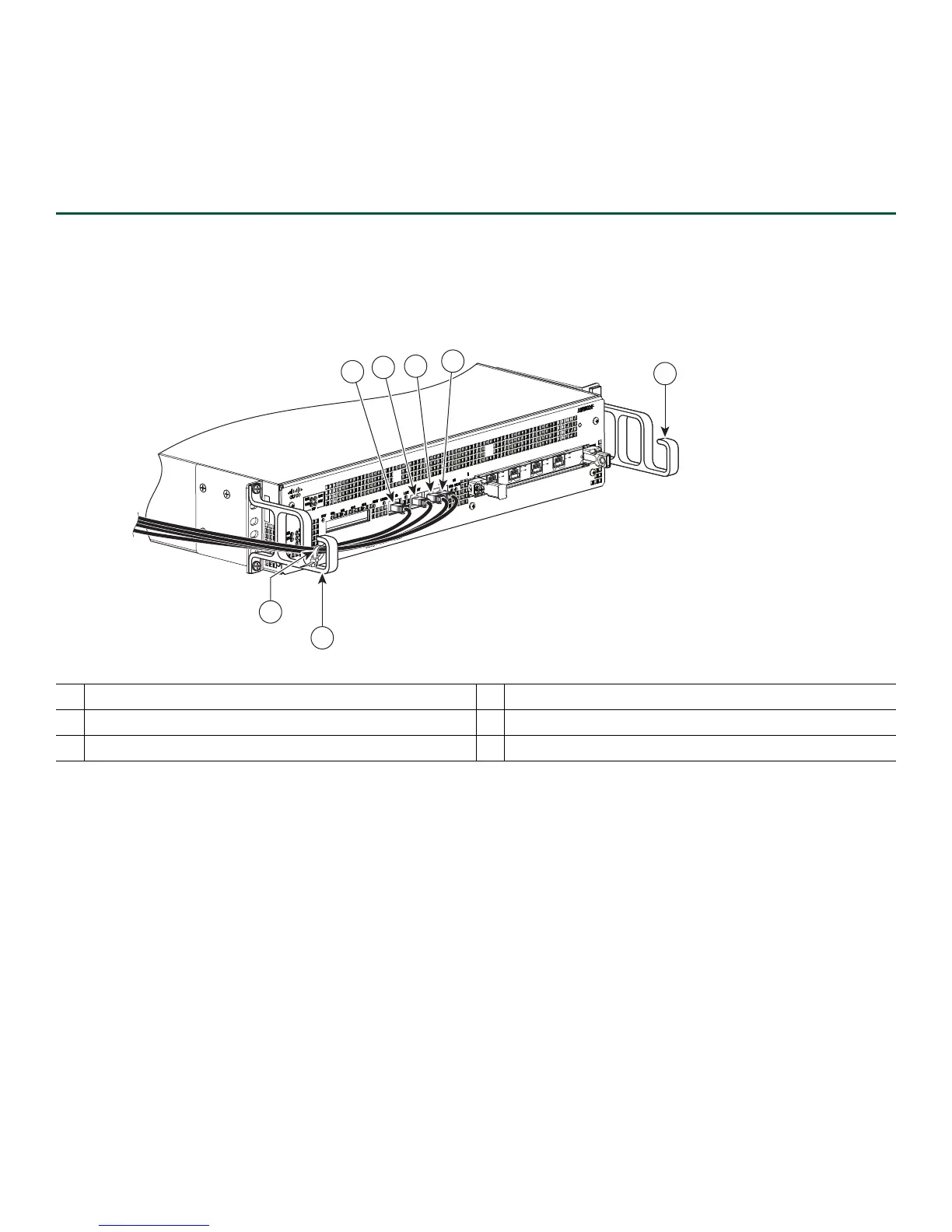
Figure 11 Cisco ASR 1002-F Integrated Route Processor Cable Management
Step 2 Route the excess cable out through either end of the bracket, coil it, and secure it to the rack using nylon cable ties or
some other mode of attachment.
Step 3 It might be necessary to bundle longer cables to avoid tangling them. Do this at the cable-management bracket or at
the rack, but leave enough slack in the cables to remove a Cisco ASR 1002-ESP-F and change cables as required. Also,
do not block the power supply air vents with cables.
1
Building Integrated Timing Source cable
4
Auxiliary cable
2
Management Ethernet cable
5
Cable-management “U” feature
3
Console cable
6
Tie wrap for cables
274949
SPA-
4X
O
C
3
-PO
S
S
T
A
T
U
S
0
1
2
3
C/
A
A
/
L
C/
A
A
/
L
C/
A
A
/
L
C
/
A
A
/
L
0
5
5
1
2
3
4
6

 Loading...