17
Table 1 describes the AC power supply LEDs on the Cisco ASR 1002-F Router.
Table 1 Cisco ASR 1002-F Router AC Power Supply LEDs
Note To connect an AC power supply to the Cisco ASR 1002-F Router, follow the steps in the Installing the AC Power Supply,
page 31.
Connect DC Power to the Cisco ASR 1002-F Router
The DC power supply input connector is a euro-style terminal block. A tab on the back of the power supply provides strain
relief to the input wires on the power supply. The connection order is negative (–), positive (+), and ground (GND).
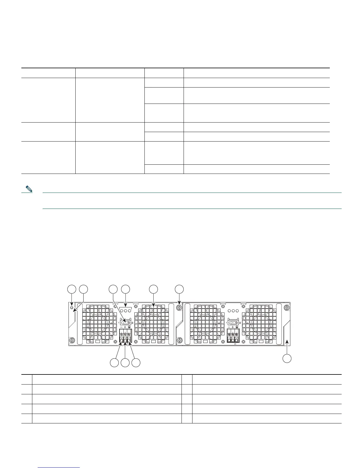
Figure 14 shows the DC power supply for the Cisco ASR 1002-F Router.
Figure 14 DC Power Supply for the Cisco ASR 1002-F Router
LED Label LED Color Description
INPUT OK Power supply activity Green The AC input voltage is greater than 85V.
Flashing For an AC input voltage between 70V and 85V the
INPUT OK LED can be on, off, or flashing.
None The AC input voltage is less than 70V or the power
supply is turned off.
FAN OK Power supply fan activity Green All fans are operational.
Red A fan failure is detected.
OUTPUT FAIL Power supply activity Red DC output voltages are within the normal operating
range. Output voltages below the minimum or above the
maximum create an output fail alarm.
Off No power to the power supply.
1
Chassis ESD socket
6
Captive installation screw
2
DC power supply slot 0 label
7
DC power supply slot 1 label
3
Standby switch
8
Earth ground lead
4
DC power supply LEDs
9
Positive ground lead
5
Fan
10
Negative ground lead
280289
OUTPUT INPUT
FAIL
OK OK
FAN
-48V/-60V 16A
This unit might have more than
one power supply connection.
All connections must be removed
to de-energize the unit.
OUTPUT INPUT
FAIL
OK OK
FAN
-48V/-60V 16A
This unit might have more than
one power supply connection.
All connections must be removed
to de-energize the unit.
9 810
4 5 63
0
1
7
1
2

 Loading...