11Telia Yritysinternet Plus Langaton
1
2
3
4 5 6 7 8 9 10 12
13
11
14
15
16
15
17 18
22 21 20 19
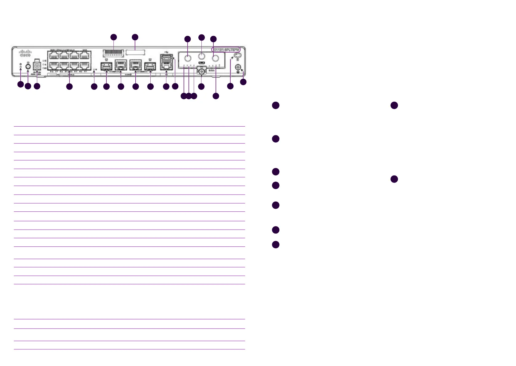
Name Note!
1 Reset button Not used
2 Power switch
3 Power cable connector
4 Ethernet switch, ports 0/1/0 – 0/1/7 Ports for connecting customer devices
5 Wi-Fi status
6 GE 0/0/1 port –SFP Not used
7 GE 0/0/1 port –RJ45 Not used
8 GE 0/0/0 – RJ45 Ethernet WAN (Internet), cannot be used for connecting
9 GE 0/0/0 – SFP Fibre WAN (Internet), cannot be used for connecting
10 Console port
11 USB 2.0 port Not used
12 LTE Module installed The module and SIM card must not be removed
13 Kensington lock
14 Earthing point
15
LTE antenna connectors – 2 pcs, Main and
Diversity
Both antennas must be connected
16 GPS antenna connector Not used
17 CLEI ID Common Language Equipment Identifier (CLEI)
18 Device serial number
19 LTE RSSI/Mode
Green = The device is connected to an LTE (4G) network
Orange = The device is connected to a 3G network
1 LED lit = Poor mobile network reception
2 LEDs lit = Low mobile network reception
3 LEDs lit = Average mobile network reception
4 LEDs lit = Good mobile network reception
20 GPS Off = GPS positioning feature is not enabled (=normal status)
21 LTE Data/SIM 0 and 1
Green flashing in the other = Data is being transferred over the
mobile data connection
22 Status Green = The router works normally (=normal status)
Figure 6. Interfaces on the back of a C1131-8PLTEPW + PoE router
C1131-8PLTEPW + PoE
router set-up
Connect both LTE antennas to the
connectors numbered with 15 in figure 6.
Note! Both antennas must be connected
to ensure mobile reception.
Connect the power cable to the
power supply and the power supply
to the customer-premises equipment,
connector 3 in figure 6.
Turn the device on, switch 2 in figure 6.
Wait for approximately 10 minutes until
the device has started.
Check the mobile network reception with
the front panel indicators (see figure 6),
indicator light 19.
Your connection is ready for use.
Use ports 0/1/2–0/1/7 to connect LAN
devices to the firewall-protected default
network (see figure 6), connectors 4.
1
2
3
4
5
6
7
8
The supplementary wireless local area
network service (WLAN) uses the
firewall-protected default network. The
settings required using the service: The
SSID and encryption key are delivered
on a technical form with the delivery
and can also be found on a label on the
device. The wireless access point takes
approximately an additional 10 minutes
to start after the router starts.
If a supplementary Avoin Internet (Open
Internet) service has been ordered for
the subscription, it is available in all LAN
ports from 0/1/2 to 0/1/7 (see figure 6),
connectors 4. The IP addresses required
for the supplementary Avoin Internet
(Open Internet) connection service have
been delivered with the technical form
in connection with the delivery. The IPv4
addresses used in the supplementary
Avoin Internet (Open Internet) service
for LAN devices must be configured
manually. If you want to distribute IPv4
addresses used in the supplementary
Avoin Internet (Open Internet) service by
the device’s DHCP server, you must select
the supplementary service Räätälöity
DHCP (Custom DHCP).
9
 Loading...