13Telia Yritysinternet Plus Langaton
C1117-4PMLTEW
router set-up
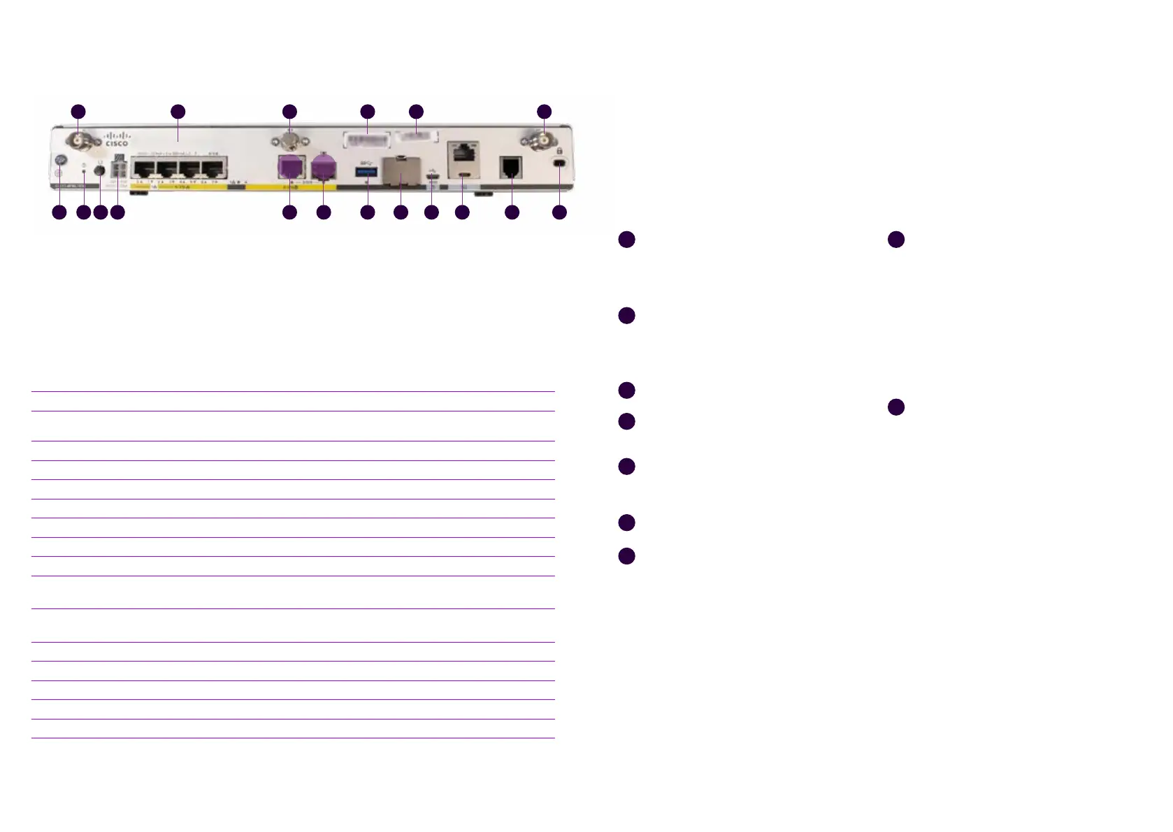
Connect both LTE antennas to the
connectors numbered with 1 in figure 7.
Note! Both antennas must be connected
to ensure mobile reception.
Connect the power cable to the
power supply and the power supply
to the customer-premises equipment,
connector 9 in figure 7.
Turn the device on, switch 8 in figure 7.
Wait for 10 minutes until the device has
started.
Check the mobile network reception with
the front panel indicators, indicator light
5 in figure 4.
Your connection is ready for use.
Use ports 0/1/0–0/1/3 to connect LAN
devices to the firewall-protected default
network (see figure 7), connectors 2.
1
2
3
4
5
6
7
8
The supplementary wireless local area
network service (WLAN) uses the
firewall-protected default network. The
settings required using the service: The
SSID and encryption key are delivered
on a technical form with the delivery
and can also be found on a label on the
device. The wireless access point takes
approximately an additional 10 minutes
to start after the router starts.
If a supplementary Avoin Internet (Open
Internet) service has been ordered for
the subscription, it is available in all LAN
ports from 0/1/0 to 0/1/3 (see figure 7),
connectors 2. The IP addresses required
for the supplementary Avoin Internet
(Open Internet) connection service have
been delivered with the technical form
in connection with the delivery. The IPv4
addresses used in the supplementary
Avoin Internet (Open Internet) service
for LAN devices must be configured
manually. If you want to distribute IPv4
addresses used in the supplementary
Avoin Internet (Open Internet) service by
the device’s DHCP server, you must select
the supplementary service Räätälöity
DHCP (Custom DHCP).
9
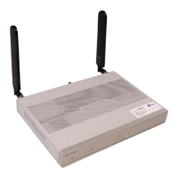
This section describes the Cisco C1117-
4PMLTEW router main connections.
The C1117-4PMLTEW router’s front looks
similar to the front of the C1111-8PLTEW router.
The indicator lights on the front panel and
1
6 7 9 10 11 12 13 14 15 16 178
12 4 53
Figure 7: Cisco C1117-4PMLTEW rear connections
Name Note!
1 LTE antenna connectors – 2 pcs, Main and Diversity Both antennas must be connected
2 Ethernet switch, ports 0/1/0–0/1/3 Ports for connecting the client’s devices
3 GPS antenna connector Not used
4 CLEI ID Common Language Equipment Identifier (CLEI)
5 Device serial number
6 Earthing point
7 Reset button Not used
8 Power switch
9 Power cable connector
10 GE 0/0/0 – RJ45
Ethernet WAN (Internet), cannot be used for con-necting
LAN devices
11 GE 0/0/0-SFP
Fibre WAN (Internet), cannot be used for connecting LAN
devices
12 USB 3.0 -port Not used
13 SIM card slots Do not open – The SIM card must not be removed
14 LTE Diagnostic port (RSVD) Not used
15 RJ45/Micro USB console
16 DSL connector Not used
17 Kensington lock
their interpretation are identical. Description of
the indicators are on page 7, figure 4.