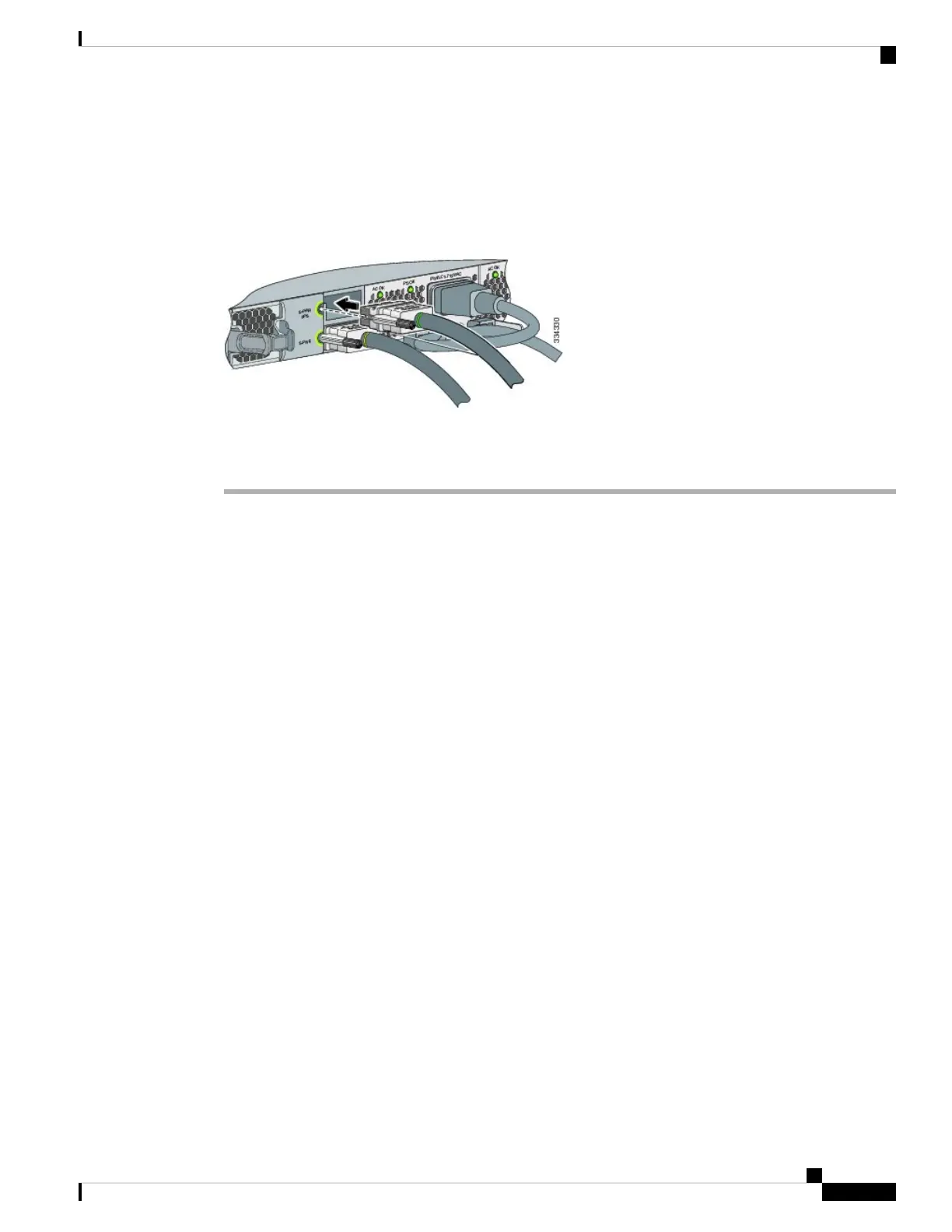
Step 2 Connect the end of the cable with a green band to either StackPower port on the first switch. Align the connector
correctly, and insert it into a StackPower port on the switch rear panel.
Step 3 Connect the end of the cable with the yellow band to another switch (to configure StackPower power sharing).
Step 4 Hand-tighten the captive screws to secure the StackPower cable connectors in place.
Figure 33: Connecting the StackPower Cable to a StackPower Port
Removing and installing the StackPower cable can shorten its useful life. Do not remove and insert
the cable more often than is absolutely necessary.
Caution
Installing a Network Module in the Switch
See these sections for information on network modules:
• Installing Network Modules, on page 59
Installing and Removing SFP, SFP+ and QSFP+ Modules
See these sections for information on SFP, SFP and QSFP+ modules:
• Installing SFP and SFP+ Modules, on page 65
• Removing SFP and SFP+ Modules, on page 66
• Cisco 40-Gigabit QSFP+ Transceiver Modules Installation Note
Connecting Devices to the Ethernet Ports
• 10/100/1000 Port Connections, on page 49
• PoE+ and Cisco UPOE Port Connections, on page 50
10/100/1000 Port Connections
The switch 10/100/1000 port configuration changes to operate at the speed of the attached device. If the
attached ports do not support autonegotiation, you can manually set the speed and duplex parameters.
Catalyst 3850 Switch Hardware Installation Guide
49OL-26779-05
Switch Installation
Installing a Network Module in the Switch