8
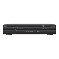
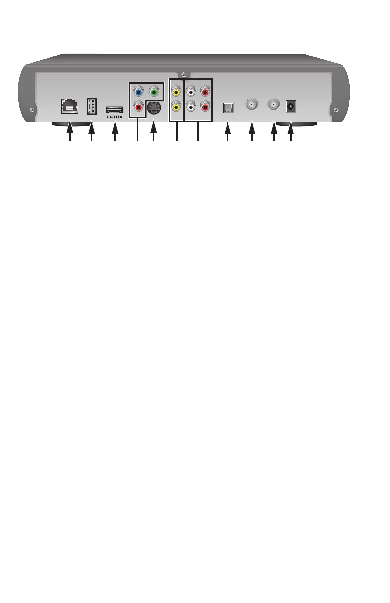
Back Panel Connectors
Note: Image may vary from actual product
T13268
Pb Y
Pr
VIDEO
OUT
AUDIO
OUT
TO WALL
(VIDEO IN)
NETWORK USB
OPTICAL
TO TV
(VIDEO OUT)
POWER
S-VIDEO
LR
9 101 2 3 5 8 114 76
1 Network Connect to the Ethernet (CAT-5) network in your home, if applicable
2 USB Port USB connector
3 HDMI Connect an HDTV HDMI™ (High-Defi nition Multimedia Interface)
cable from the HDTV to the HDMI port. HDMI supports both digital
audio and video
4 YPbPr Connect the set-top to the component video input (YPbPr) on the
HDTV
5 S-Video Connect an S-Video cable to send an S-Video signal to your TV or
VCR. This signal is standard defi nition but higher quality than other
SDTV connections
6 Video Out Connect to either a VCR or connect to another set of inputs
(composite) on your HDTV or SDTV
Note: Two video output connectors are provided. Typically, one
output is connected to the TV, and the other output is used to
connect to a home theater system, DVD recorder, or VCR
7 Audio Out Connect RCA-type cables to Audio Out to send analog audio
(L/R) signals (left and right) to a TV with stereo inputs or to a stereo
amplifi er
Note: Two sets of audio out connectors are provided. Typically, one
set of outputs is connected to the TV, and the other set is used to
connect to a home theater system, DVD recorder, or VCR
8 Optical Connect an optical cable to send a digital audio signal to a
surround-sound receiver or other digital audio device
9 To TV* Connect to TV. This is a channel 3/4 output. You must set the
(Video Out) channel on your TV to the correct channel (either channel 3 or 4)
10 To Wall* Connect the set-top to in-house coaxial wiring, if applicable.
(Video In) This signal is used to receive an Ethernet-over-coaxial signal.
11 Power Connect the DC output of the AC power adapter (provided) to
deliver power to the set-top
* May not be available on all models.
**