Cisco IE 3010 Switch Getting Started Guide
18
Cisco IE 3010 Switch Getting Started Guide
78-19582-02
Connecting to the Power Source
Prepare the power cable.
Warning
This unit might have more than one power supply connection. All connections
must be removed to de-energize the unit.
Statement 1028
Warning
This product relies on the building’s installation for short-circuit (overcurrent)
protection. Ensure that the protective device is rated not greater than:
AC: 5 A, DC: 15 A.
Statement 1005
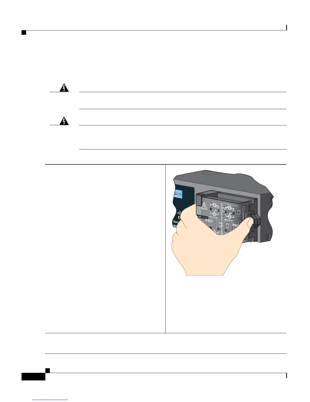
Step 1
Locate the switch power-input terminal.
The terminal screws are labeled on the
power-input terminal cover.
AC power:
Identify the line and neutral AC-power
terminal screws. The line terminal screw is
labeled L, and the neutral terminal screw is
labeled N.
DC power:
Identify the positive and negative DC-power
terminal screws. The positive terminal screw
is labeled +, and the negative terminal screw
is labeled –.
Note The terminal screws for power-supply
module 1 are on the side labeled
PSU1, and the terminal screws for
power-supply module 2 are on the
side labeled PSU2. Make sure that
you connect the wires to the correct
terminal screws.
Step 2
Locate the AC and DC circuit breakers, turn them OFF, and tape them in the OFF position.
Note Do not connect the switch to a power source that has an ON/OFF switch.
207221
100-240V~, 50-60Hz, 2A
100-240V~, 50-60Hz, 2A
2A2A
10A
10A
5
5
 Loading...


