5
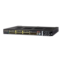
Product Documentation and Compliance Information for the Cisco IE 4010 and Cisco IE 5000 Switches—Documentation sur le
produit et informations relatives à la conformité pour les commutateurs Cisco IE 4010 et Cisco IE 5000.
Installing a Power-Supply Module—Installation d'un module d'alimentation
Attention Cet équipement est fourni en tant qu'équipement « ouvert ». Il doit être installé dans un boîtier
adapté à ces conditions environnementales spécifiques et sa conception doit permettre
d'empêcher toute blessure corporelle pouvant résulter de l'accès aux parties actives. L'intérieur
du boîtier doit être accessible à l'aide d'un outil uniquement.
Au minimum, le boîtier doit être conforme aux normes IP 54 ou NEMA type 4.
Énoncé
1
063
Attention Utilisez des câbles d'alimentation à paires torsadées résistant aux températures ambiantes
supérieures à 30 °C (86 °F).
Énoncé 1 067
Attention Lorsque cet équipement est utilisé dans une zone dangereuse de Classe I, Zone 2, Division 2, il
doit être installé selon une méthode de câblage appropriée conforme aux codes électriques en
vigueur.
Énoncé 1069
Attention Danger d'explosion : assurez-vous que la zone est exempte de tout danger avant d'installer,
entretenir ou remplacer l'unité. Énoncé 1 082
Remarque Cet équipement a été testé par UL pour déterminer les dangers d'explosion, d'incendie, de choc et de
mort, conformément aux réglementations locales. La certification délivrée par UL ne porte pas sur la
performance ou la fiabilité des matériels GPS, des logiciels GPS, ou tout autre aspect associé au GPS
dans cette catégorie. Par conséquence, UL n'offre pas de représentation, de garantie ou de certification
relative à la performance ou la fiabilité des fonctions GPS d'un équipement appartenant à cette catégorie.
Installing a Power-Supply Module—Installation d'un module
d'alimentation
English
This procedure is for installing a power-supply module in the PSU1 or PSU2 slot.
Warning The covers are an integral part of the safety design of the product. Do not operate the unit
without the covers installed.
Statement 1077
Warning This unit might have more than one power supply connection. All connections must be removed
to de-energize the unit.
Statement 1028
Caution Equipment installation must comply with local and national electrical codes.
Equipment That You Need
• Ratcheting torque flathead screwdriver that exerts up to 15-inch pound (in-lb) of torque
• Ring, spade, or flanged spade terminal (terminals should be insulated)
– Ring terminal [such as Tyco part number 2-34158-1 for 16–14 AWG (1.31-2.08-mm
2
) or 2-34852-1 for 12–10
AWG (3.31-5.26-mm
2
) wire]
– Spade terminal [such as Tyco part number 54367-2 for 16–14 AWG (1.31-2.08 mm
2
) wire]
– Flanged spade terminal [such as Tyco part number 2-324165-1 for 16–14 AWG (1.31-2.08-mm
2
) wire or
1-324581-1 for 12–10 AWG (3.31-5.26-mm
2
) wire]
Note For IP-30 compliance:
- Use the 16-14 AWG (1.31-2.08-mm
2
) wire and appropriate terminals for the AC or high-voltage DC power
supply
- Use the12-10 AWG (3.31-5.26-mm
2
) wire and appropriate terminals for the low-voltage DC power supply

 Loading...