21
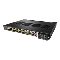
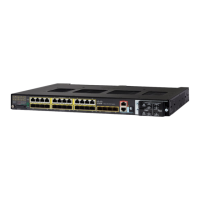
Product Documentation and Compliance Information for the Cisco IE 4010 and Cisco IE 5000 Switches—Documentation sur le
produit et informations relatives à la conformité pour les commutateurs Cisco IE 4010 et Cisco IE 5000.
Installing a Power-Supply Module—Installation d'un module d'alimentation
Reliez l'autre extrémité du câble positif (celui connecté à +) à la borne positive sur la source d'alimentation CC et reliez
l'autre extrémité du câble négatif (celui connecté
à –) à la borne négative sur la source d'alimentation CC.
10. Fermez le couvercle du terminal d'alimentation. Serrez la vis à un couple de 0,79 Nm (7 po-lb) à l'aide d'un tournevis
à tête plate à cliquet.
11. Mettez le circuit CA ou CC sous tension, vérifiez que le voyant PSU1 ou PSU2 du commutateur et le voyant OK du
module d'alimentation sont verts.
12. Si vous avez deux alimentations, répétez les étapes 1 à11. Reportez -vous au guide du logiciel du commutateur
pour configurer les paramètres du module d'alimentation.
Removing the Power-Supply Module—Retrait du module d'alimentation
English
The power supply modules are NOT hot-swappable. Turn off the input power to the switch before removing either power
supply modules.
Caution Sparking may occur if power is not turned off while swapping the power supply module. This can cause
an explosion in hazardous environment
Step 1 Locate the circuit breakers, turn them OFF and tape them in the OFF position.
Note If the power is not off at the AC or DC circuit breaker, do not touch the power-input terminal.
Step 2 Verify that the PSU LED and PSU OK LED is blinking red or is off.
Step 3 Use a Phillips screwdriver to loosen the captive screws that secure the power-supply module to the
switch. See Figure 3-25.
Warning Hot surface.
Statement 1079
Figure 3-25 Removing the Screws
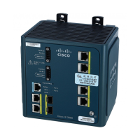
Cisc o IE 3010
Sw itch Series
208384
 Loading...


