16
Product Documentation and Compliance Information for the Cisco IE 4010 and Cisco IE 5000 Switches—Documentation sur le
produit et informations relatives à la conformité pour les commutateurs Cisco IE 4010 et Cisco IE 5000.
Installing a Power-Supply Module—Installation d'un module d'alimentation
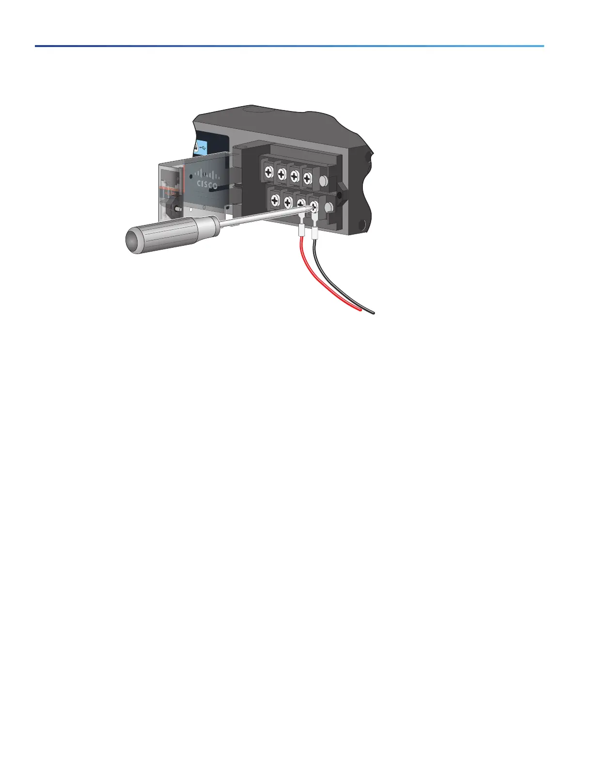
Figure 18 Connecting the Wires to the Low-Voltage DC Power (PSU2)
1. Torque the captive screws (above the wires) to 7 in-lb (0.79 Nm).
2. AC power
Connect the other end of the line wire (the one connected to L) to the line terminal on the AC-power source, and connect
the other end of the neutral wire (the one connected to N) to the neutral terminal on the AC power source.
DC power
Connect the other end of the positive wire (the one connected to +) to the positive terminal on the DC-power source,
and connect the other end of the negative wire (the one connected
to –) to the negative terminal on the DC power source.
3. Close the power-input terminal cover. Use a ratcheting torque screwdriver to torque the screw to 7 in-lb (0.79 Nm).
4. Turn on the power at the AC or DC circuit, verify that the PSU1 or PSU2 LED on the switch and PSU OK LED on the
power-supply module are green.
5. If you have two power supplies, repeat Step 1 through Step 11. See the switch software guide for information on
how to configure the power supply settings.
Français
Avant de brancher la source d'alimentation, consultez les avertissements dans cette section :
Avertissement La plage de tension d'entrée du module d'alimentation CA est comprise entre 85 VDC et 264 VDC et
entre 88 VCC et 300 VCC. Pour le module d'alimentation CC, la plage est comprise entre 18 VDC à 60
VDC. Pour une sécurité et des performances optimales, assurez-vous que les tensions d'entrée sont
comprises dans ces plages.
Attention Un système de protection contre les risques de courts-circuit (surintensité) doit être installé dans
le bâtiment. Assurez-vous que la protection porte l'homologation maximale :
CA : 5 A, CC : 15 A
Énoncé 1 005

 Loading...


