15
Product Documentation and Compliance Information for the Cisco IE 4010 and Cisco IE 5000 Switches—Documentation sur le
produit et informations relatives à la conformité pour les commutateurs Cisco IE 4010 et Cisco IE 5000.
Installing a Power-Supply Module—Installation d'un module d'alimentation
Note Use the appropriate terminal screws, depending on whether you are installing a high-voltage (AC or DC)
or a low-voltage (DC) power supply.
Note If you have a low-voltage DC power-supply module, connect the wires to the terminals labeled Lo. If
you have a high-voltage DC power-supply module, connect the wires to the terminals labeled Hi.
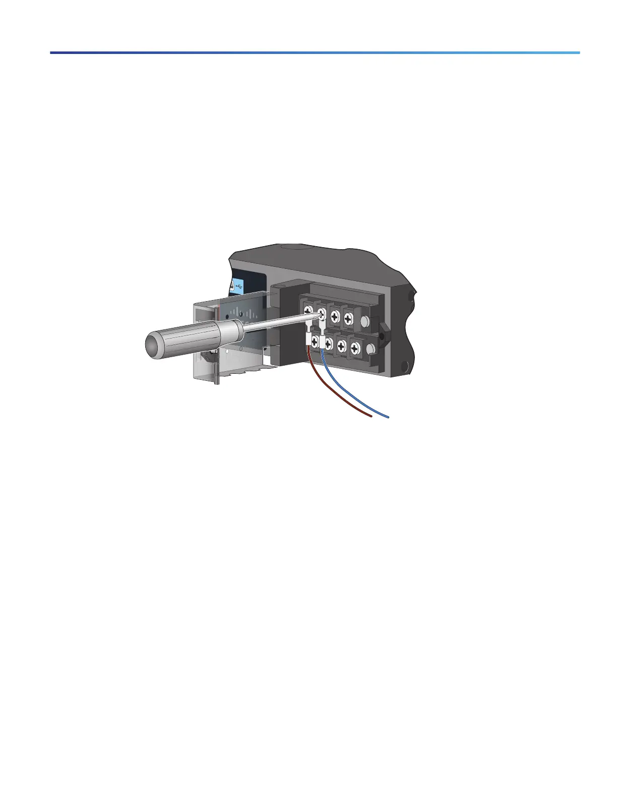
7. To connect the AC power:
a. Connect the line wire into the terminal screw labeled L and the neutral wire into the terminal screw labeled N.
b. Make sure that you cannot see any wire lead. Only wire with insulation should extend from the terminal screw.
Figure 17 Connecting the Wires to the High-Voltage AC Power (PSU1)
To connect the DC power:
a. Connect the positive wire into the terminal screw labeled +, and the negative wire into the terminal screw
labeled –.
b. Make sure that you cannot see any wire lead. Only wire with insulation should extend from the terminal screw.
100-240V~, 50-60Hz, 2.2A
100-240V~, 50-60Hz, 2.2A
Cisco IE 3010
208381

 Loading...


