6
Getting Started and Product Document of Compliance for the Cisco IR809 Integrated Services Router
78-100612-01A0
Connecting DC Power
Warning
When you connect or disconnect the power and/or alarm connector with power applied, an electrical
arc can occur. This could cause an explosion in hazardous area installations. Be sure that all power
is removed from the equipment and any other circuits. Be sure that power cannot be accidentally
turned on or verify that the area is nonhazardous before proceeding.
Statement 1058
Warning
Explosion Hazard—The area must be known to be nonhazardous before installing, servicing, or
replacing the unit.
Statement 1082
Warning
Explosion Hazard—Substitution of components may impair suitability for Class I, Division 2/Zone 2.
Statement 1083
Warning
Connect the unit only to DC power source that complies with the safety extra-low voltage (SELV)
requirements in IEC 60950 based safety standards.
Statement 1033
Note Maximum DC input operating range is 9.6-60Vdc, 0.5-1.5A
Plugs and Pin-Outs
The following is a brief overview of connecting to DC power. Details can be found in the Cisco IR809
Integrated Services Router Hardware Installation Guide and should be understood before beginning. See
Related Documentation, page 3.
The IR809 ships with a DC power accessory kit that contains a 4-pin screw on connector.
The power entry receptacle is on the IR809. The power connector plug is shown in Figure 1. The Power
Receptacle is shown in Figure 2
Descriptions are shown in Figure 3.
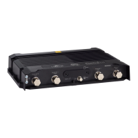
Step 5
Insert the ground screw into the grounding point shown in the graphic.
Step 6
Use a ratcheting torque screwdriver to tighten the ground screw and ring terminal to the router side panel to 3.5 in-lb
(0.4 N-m). The torque should not exceed 3.5 in-lb (0.4 N-m).
Step 7
Attach the other end of the ground wire(#1 in the graphic above) to a grounded bare metal surface, such as a ground
bus, a grounded DIN rail, or a grounded bare rack.