7
Getting Started and Product Document of Compliance for the Cisco IR809 Integrated Services Router
78-100612-01A0
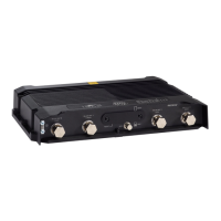
Figure 1 Power Connector Plug
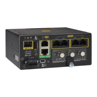
Figure 2 Power Receptacle
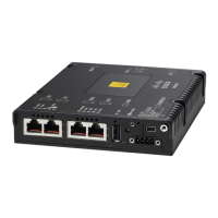
Figure 3 Power connector Descriptions
To connect DC power:
Pin Number Name Description Color
1 DC In + DC Power In (BAT+) Red
2 DC In - DC Power Return (GND-) Black
3 AC Alarm Common N/A
4 AI Alarm Input N/A
Step 1
Locate the power and alarm connector on the router front panel. The pins
and their function are found in Figure 3.
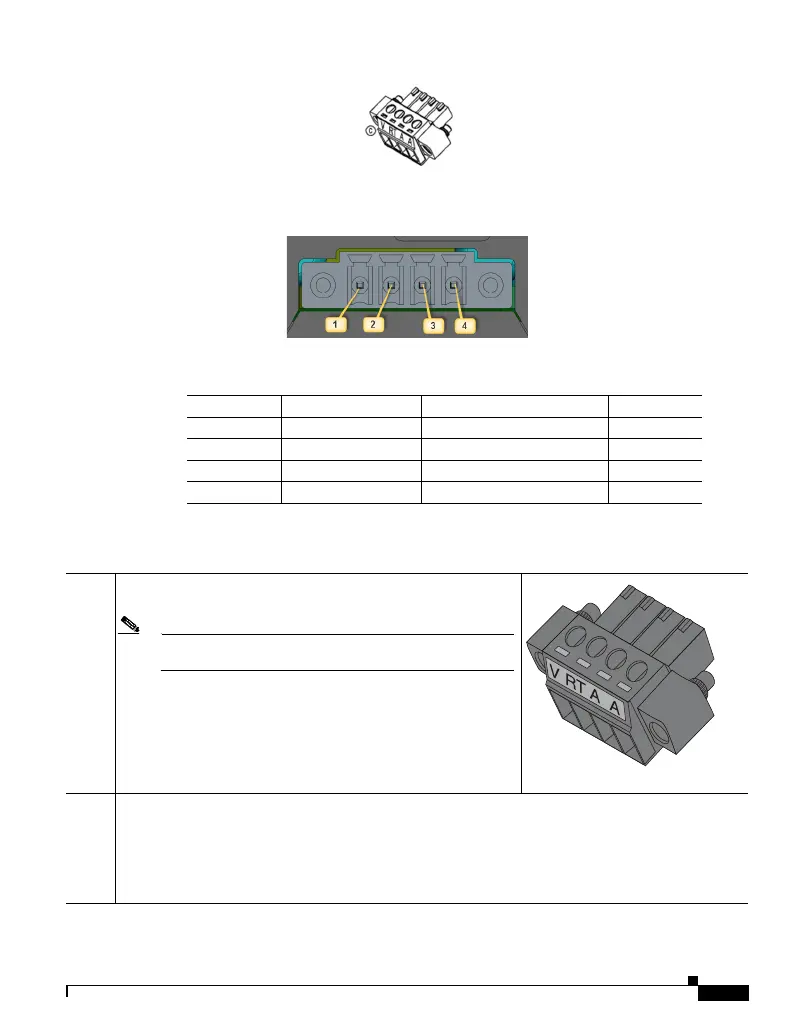
Note Your connector may not have the labels V RT A A appear on it.
The pins are 1-4 from left to right.
In the labeled connector, the pins are:
V—Positive DC power connection
RT— Return DC power connection
A— Alarm Common
A— Alarm Input
Step 2
Identify the connector positive and return DC power connections. The connections are:
• 1—Positive DC power connection
• 2—Return DC power connection
• 3—Alarm Common
• 4—Alarm Input
391920