type has airflow in the opposite direction, that is, rear-chassis intake and port-side exhaust. The airflow direction
is denoted on each PSU as follows:
• Red—Port-side intake airflow
• Blue—Port-side exhaust airflow
The switch supports PSUs of only one airflow type at a time. Both PSUs have to be either port-side exhaust,
or port-side intake PSUs.
The direction of PSU airflow must match the direction of the fan module airflow.
Note
For more information on installing and removing PSUs, see Installing and Removing Power Supply Units.
LEDs
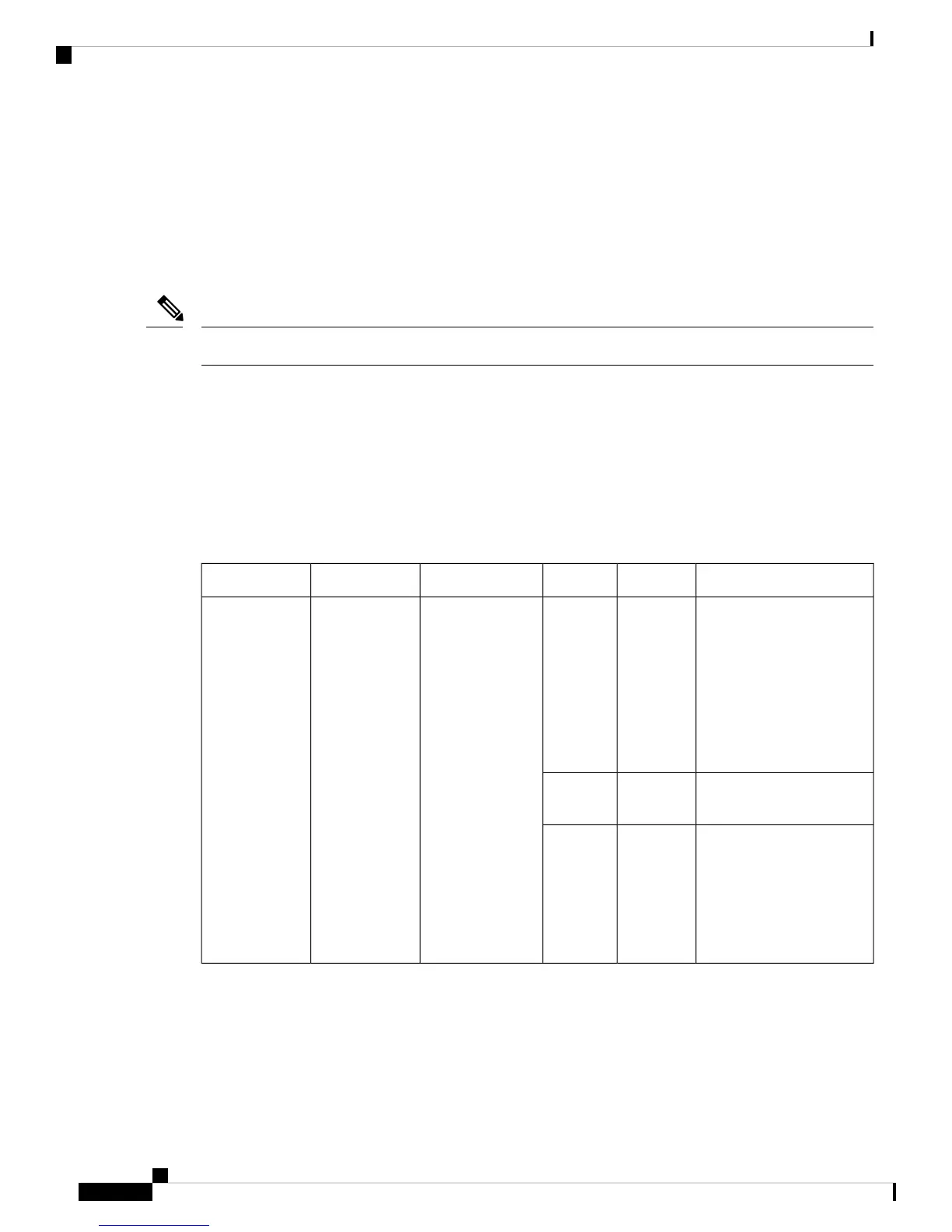
The Cisco MDS 9148T switch has LEDs on both the front and back of the switch to indicate the status of
different system components during bootup tests and online operation. The following tables describe the
location of each LED and the meaning of its color:
Table 1: Chassis Activity LEDs for a Cisco MDS 9148T Switch
StateStatusColorFunctionLocationIndicator
Either of the following
conditions exists:
• The system is not
receiving sufficient
power from the PSUs.
• The operating system
is not running.
OffOffChassis
Power/Health
Front panel of
the chassis
Power LED
Both PSUs are installed and
operational.
Solid OnGreen
Either of the following
conditions exists:
• A PSU has failed.
• A PSU has been
removed.
Solid OnRed
Cisco MDS 9148T 32-Gbps 48-Port Fibre Channel Switch Hardware Installation Guide
10
Overview of Cisco MDS 9148T Fibre Channel Switch
LEDs