Do you have a question about the Cisco Meraki MR42 and is the answer not in the manual?
Details the physical characteristics, interfaces, power, and environment of the MR42.
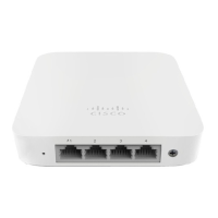
Lists the physical ports available on the MR42 access point.
Specifies power requirements and consumption for the MR42.
Outlines the operating temperature and humidity limits for the device.
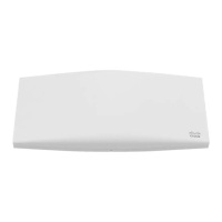
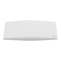
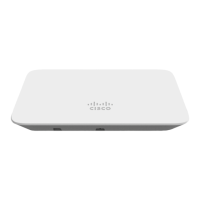
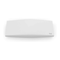
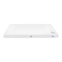
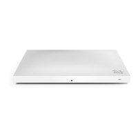
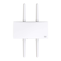
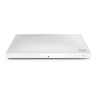
Illustrates the physical layout and key features of the MR42 device.
Outlines methods for physically securing the access point after installation.
Describes the Gigabit Ethernet RJ45 port for WAN uplink.
Crucial safety precautions and electrical warnings for installation.
Steps to complete before beginning the on-site installation process.
Overview of adding and configuring the MR42 in the Meraki dashboard.
Lists the necessary tools required for the installation process.
Guidance on selecting the optimal location for MR42 placement.
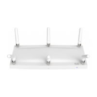
Instructions for attaching the MR42 mount cradle to various surfaces.
Steps for mounting the MR42 onto a drop ceiling T-rail.
Instructions for mounting the cradle to electrical junction boxes.
Details various methods for powering the MR42 access point.
Describes the multi-color LED and its meanings, including Run Dark mode.
Methods for physically securing the MR42 to its mounting location.
Steps to verify correct operation and test wireless coverage.
Common steps for resolving basic connectivity issues.
Steps to verify the functionality of the Ethernet port.
Guidance on verifying static IP address settings.
Information regarding the warranty coverage for the MR42 device.
How to get further assistance and find additional documentation.
The Cisco Meraki MR42 is a cloud-managed access point designed for high-capacity and high-density wireless environments. It supports dual-band 802.11ac and features a unique third radio dedicated to optimizing the RF environment and enhancing security. This device is suitable for demanding environments such as offices with many workspaces.
The MR42 serves as a central component in a wireless network, providing Wi-Fi connectivity to client devices. Its primary function is to broadcast SSIDs, allowing users to connect to the network. The cloud-managed aspect means that configuration, monitoring, and troubleshooting are handled remotely through the Meraki dashboard, simplifying network administration. The dedicated third radio actively works to optimize the RF environment, which can include tasks like interference detection and mitigation, ensuring a more stable and efficient wireless experience. This radio also contributes to securing the airwaves by potentially identifying and addressing security threats.
The MR42 offers flexible power options, supporting Power over Ethernet (PoE) via 802.3at (with functionality-restricted 802.3af mode supported) or a 12V DC input. This flexibility allows for deployment in various locations, depending on power infrastructure availability. When powered by 802.3af, the device operates in a low-power mode, disabling the Air Marshal radio and reducing transmit streams on the 2.4 GHz band, though it still maintains full 802.11ac capabilities.
Installation is designed to be straightforward, utilizing a mount cradle that can be attached to walls, solid ceilings, drop ceilings, or various electrical junction boxes. The mount cradle includes a built-in level tool to aid in proper alignment during installation. For drop ceiling installations, a specific mounting accessory kit is provided, including clips and screws to secure the device to T-rails of different sizes. The device can also be simply placed on a desk or shelf, using its non-scratch rubber feet, without requiring the mount cradle.
The MR42 features an LED indicator that provides visual feedback on its operational status. Different colors and blinking patterns indicate various states, such as booting, initializing, upgrading firmware, operating in gateway mode with or without clients, or experiencing an uplink issue. For enhanced security or reduced visibility, the device can be configured to operate in "Run Dark" mode, which disables the LED indicator.
Before deployment, it's recommended to configure the network in the Meraki dashboard, add the APs using their serial numbers or order information, and place them on a map or floor plan. A firmware upgrade is also advised prior to mounting to ensure optimal performance. The device automatically checks for and installs firmware updates when connected to power and the internet, indicated by a blinking orange LED during the upgrade process.
IP address assignment can be dynamic via DHCP or static. For dynamic assignment, the DHCP server can be configured to reserve static IP addresses for the APs based on their MAC addresses. Static IP addresses can also be configured directly through the AP's local web server by connecting to its SSID and accessing http://my.meraki.com or http://10.128.128.128. This allows for manual configuration of IP address, net mask, gateway, and DNS servers.
The MR42 incorporates several features for physical security and troubleshooting. For physical security, it offers two options: a security screw and a Kensington lock hard point. The included security screws can be used to secure the access point to its mount cradle, preventing accidental dislodging and theft. The Kensington lock hard point allows the device to be secured to a permanent structure using a standard Kensington lock cable.
Basic troubleshooting steps are provided to address connectivity issues. These include resetting the access point, performing a factory reset by holding the reset button for five seconds, and trying different cables or testing cables on other devices. The LED indicators are crucial for diagnosing issues, as they convey information about the device's state.
To verify radio functionality, the AP can be switched into repeater mode by disconnecting its Ethernet cable. In this mode, it will broadcast an SSID appended with "-scanning," allowing a client device to connect and access my.meraki.com to confirm radio operation. If the AP is then placed near a working gateway AP, it should connect as a repeater, and its status will be visible in the Meraki dashboard.
Ethernet port functionality can be checked by connecting a computer directly to the AP's Ethernet port. The Ethernet LED should turn solid green or blue, and the computer should obtain an IP address via DHCP. If the LED does not light up, troubleshooting involves swapping cables or trying a different Ethernet port if available.
For static IP configuration issues, the troubleshooting process involves disconnecting the Ethernet cable, associating with the AP's SSID, accessing my.meraki.com, verifying the MAC address, and then checking the static IP configuration settings on the "Static IP configuration" tab. The username for logging in is the AP's serial number (case-sensitive, including dashes), with no password.
Cisco Meraki provides support for hardware issues, including RMA processes for failed devices under warranty. Access to original packaging with serial number and order information may be required for hardware replacements. Additional support and documentation are available through the Meraki dashboard's "Help" section and the documentation website.
| 2.4 GHz | Yes |
|---|---|
| Bandwidth | 5 GHz |
| Modulation | 256-QAM |
| Frequency band | 2.412 - 5.825 GHz |
| Networking standards | IEEE 802.11a, IEEE 802.11ac, IEEE 802.11b, IEEE 802.11e, IEEE 802.11g, IEEE 802.11h, IEEE 802.11i, IEEE 802.11k, IEEE 802.11n, IEEE 802.11r, IEEE 802.11u |
| Virtual LAN features | Tagged VLAN |
| Ethernet LAN data rates | 10, 100, 1000 Mbit/s |
| Maximum data transfer rate | 1900 Mbit/s |
| WAN connection | Ethernet (RJ-45) |
| USB 2.0 ports quantity | 0 |
| Ethernet LAN (RJ-45) ports | 1 |
| Security algorithms | AES, TKIP |
| Antenna features | Integrated antenna |
| Antenna direction type | Omni-directional |
| AC input voltage | 12 V |
| Power consumption (max) | 20 W |
| Placement | Ceiling, Table, Wall |
| Product color | White |
| LED indicators | Status |
| Cable lock slot type | Kensington |
| Operating temperature (T-T) | 0 - 40 °C |
| Operating relative humidity (H-H) | 5 - 95 % |
| Harmonized System (HS) code | 85176990 |
| Depth | 155.8 mm |
|---|---|
| Width | 253.4 mm |
| Height | 37.1 mm |
| Weight | 700 g |