Do you have a question about the Cisco MS225-24 and is the answer not in the manual?
Details the components included in the Rack Mounting Kit for the MS225 series switches.
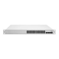
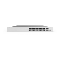
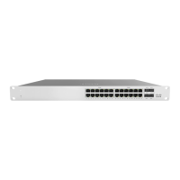
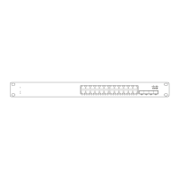
Diagram and description of the front panel for the MS225-24 series switch.
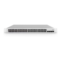
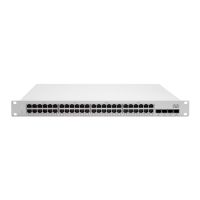
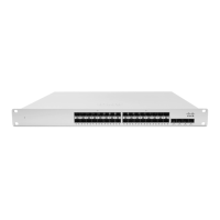
Diagram and description of the front panel for the MS225-48 series switch.
Describes LED status for Power and Restore functions, including meanings and states.
Details the LED status for switch ports and the meaning of the 'Off' state.
Describes LED status for Management Interface and Stack Ports, and their meanings.
Explains the 22-Pin Redundant Power Supply Connector and its purpose for failover.
Lists supported Cisco part numbers and descriptions for the RPS2300 for power redundancy.
Information on cross-model stacking support and connecting MS switches in a physical stack.
Details rack mount kit usage, airflow considerations, and optional mid-mount brackets.
| Model | MS225-24 |
|---|---|
| Product Type | Switch |
| Port Count | 24 |
| Uplink Ports | 4 x 1G SFP |
| Form Factor | Rack-mountable |
| Manageable | Yes |
| Layer | Layer 2 |
| Jumbo Frame Support | Yes |
| Jumbo Frame Size | 9216 bytes |
| Power Supply | Internal |
| Power over Ethernet (PoE) | No |
| Ports | 24 x 10/100/1000 Ethernet |
| MAC Address Table Size | 16, 000 |
| Operating Temperature | 32°F to 104°F (0°C to 40°C) |
| Operating Humidity | 10% to 90% non-condensing |
| Dimensions | 1.73 x 17.5 x 10.0 in |