EasyManua.ls Logo

Cisco Meraki MS125 Series - User Manual

Cisco Meraki MS125 Series
12 pages
Print Icon
To Next Page IconTo Next Page
Loading...
MS125 Series Installation Guide
About this Guide
This guide provides instruction on how to install and configure your MS125 series switch. This guide also provides mounting instructions and limited
troubleshooting procedures. For more switch installation guides, refer to the switch installation guides section on our documentation website.
Model number Description
MS125-24 Layer-2 24-port gigabit Ethernet switch with 4 SFP+ interfaces
MS125-24P Layer-2 24-port gigabit Ethernet 370W PoE switch with 4 SFP+ interfaces
MS125-48 Layer-2 48-port gigabit Ethernet switch with 4 SFP+ interfaces
MS125-48LP Layer-2 48-port gigabit Ethernet 370W PoE switch with 4 SFP+ interfaces
MS125-48FP Layer-2 48-port gigabit Ethernet 740W PoE switch with 4 SFP+ interfaces
Product Overview
Physical Specifications
MS125-24 MS125-24P MS125-48 MS125-48LP
1GbE RJ45 24
24
48 48
10GbE SFP+ 4 4 4 4
Dedicated Mgmt Interface 1 1 1 1
PoE Capable - Yes, 370W - Yes, 370W
Power Supply Built-in Built-in Built-in Built-in
1
Question and Answer IconNeed help?

Do you have a question about the Cisco Meraki MS125 Series and is the answer not in the manual?

Summary

About this Guide

Product Overview

Physical Specifications

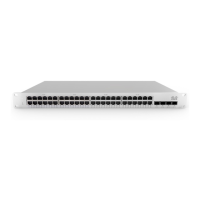
Details the physical specifications for the MS125 series switches, including ports and power.

Product Views

Front Panel

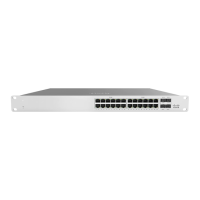
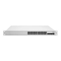
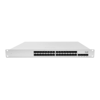
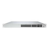
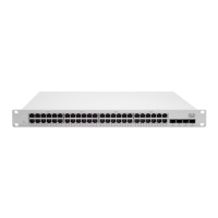
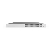
Illustrates the front panel layout and components of the MS125 series switches.

Device Details and Indicators

Back Panel

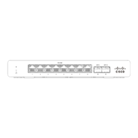
Illustrates the back panel layout and components of the MS125 series switches.

Factory Reset Button

Explains the function and procedure for using the factory reset button on the switch.

Front Panel Components

Describes the function and LED status meanings for front panel components.

Back Panel Components

Package Contents

Safety and Warnings

Pre-installation Preparation

Configure Dashboard Network

Steps to set up your Meraki dashboard network and add the switch.

Firmware Update Check

Procedure to check and update switch firmware for optimal performance post-installation.

Firewall Configuration

Guidance on configuring upstream firewall settings for Meraki switch connectivity.

IP Address Assignment

Dynamic Assignment

Configuring DHCP for static IP assignment to Meraki switches.

Static Assignment

Manual configuration of static IP, net mask, gateway, and DNS via switch web server.

DHCP Reservations

Using DHCP reservations on the server to assign static IPs to switches.

Installation Instructions

Mounting Hardware

Rack Mounting

Details on the included 1U rack mount kit and airflow considerations.

Optional Mid-Mount Bracket

Information on using an optional mid-mount bracket for 2-post rack installations.

Basic Troubleshooting

Switch Reset Procedures

Steps for troubleshooting, including performing a factory reset or reboot.

Warranty Information

Support and Additional Information

Overview

The Cisco Meraki MS125 series is a line of cloud-managed Layer-2 Gigabit Ethernet switches designed for various network environments, from small businesses to larger enterprises. These switches offer a range of port configurations and Power over Ethernet (PoE) capabilities, making them versatile for different deployment needs.

Function Description:

The MS125 series switches provide Layer-2 switching functionality, enabling efficient data forwarding within a local area network. As cloud-managed devices, they integrate seamlessly with the Meraki dashboard, offering centralized control, monitoring, and troubleshooting from any location with internet access. This cloud-based management simplifies network deployment and ongoing maintenance, eliminating the need for on-site controllers. Key functions include port management, VLAN configuration, quality of service (QoS) settings, and security features. The PoE-capable models (MS125-24P, MS125-48LP, MS125-48FP) can power connected devices such as IP phones, wireless access points, and security cameras directly over Ethernet cables, reducing cable clutter and simplifying power infrastructure. The switches also feature SFP+ interfaces for high-speed uplinks, supporting 10 Gigabit Ethernet connections to other switches or network devices.

Important Technical Specifications:

  • Models:
    • MS125-24: Layer-2 24-port gigabit Ethernet switch with 4 SFP+ interfaces.
    • MS125-24P: Layer-2 24-port gigabit Ethernet 370W PoE switch with 4 SFP+ interfaces.
    • MS125-48: Layer-2 48-port gigabit Ethernet switch with 4 SFP+ interfaces.
    • MS125-48LP: Layer-2 48-port gigabit Ethernet 370W PoE switch with 4 SFP+ interfaces.
    • MS125-48FP: Layer-2 48-port gigabit Ethernet 740W PoE switch with 4 SFP+ interfaces.
  • Physical Specifications:
    • 1GbE RJ45 Ports: 24 (MS125-24, MS125-24P) or 48 (MS125-48, MS125-48LP, MS125-48FP).
    • 10GbE SFP+ Ports: 4 for all models.
    • Dedicated Management Interface: 1 for all models.
    • PoE Capable: Yes (MS125-24P, MS125-48LP, MS125-48FP) with 370W or 740W PoE budget.
    • Power Supply: Built-in for all models.
  • Power Input: 100-240 VAC, 47-63 Hz for all models.
  • Power Consumption (Idle/Max):
    • MS125-24: 10.3 - 25.6 W
    • MS125-24P: 21.7 - 42 W (idle), 25 / 426.1 W (load)
    • MS125-48: 25 - 426.1 W (idle), 21.7 / 42 W (load)
    • MS125-48LP: 40.2 - 439.8 W (idle), 40.2 / 439.8 W (load)
    • MS125-48FP: (Not explicitly listed for idle/max, but implies higher consumption given 740W PoE)
  • Operating Temperature: 32°F - 113°F (0°C - 45°C).
  • Storage and Transportation Temperature: -4°F - 158°F (-20°C - 70°C).
  • Humidity: 5% to 95%.
  • Mounting: 1U Rack Mount (Front for all models; MS125-48LP also supports Mid-mount).
  • Fans: Built-in for all models.

Usage Features:

The MS125 series is designed for ease of use and flexible deployment.

  • Cloud Management: All configuration, monitoring, and troubleshooting are performed through the Meraki dashboard. This allows for remote management, zero-touch provisioning, and automated firmware updates.
  • Installation: The switches are 1U rack-mountable. The package includes mounting screws and cage nuts (US 12-24, INTL M5, INTL M6) and mounting washers. An optional MA-MNT-MID-1 mid-mount bracket is available for 48-port models when using 2-post racks.
  • IP Address Assignment: Switches can be assigned IP addresses dynamically via DHCP or statically. For static assignment, users can connect a client machine to the switch, access its built-in web server (http://my.meraki.com or http://1.1.1.100), and configure the IP address, net mask, gateway, and DNS servers through the "Uplink Configuration" tab. DHCP reservations are also supported for assigning static IPs via the upstream DHCP server.
  • Status Indicators:
    • Power LED: Solid orange indicates the switch is unable to connect to the Meraki cloud. Flashing white means a firmware upgrade is in process. Solid white signifies the switch is fully operational and connected to the Meraki cloud. Off means no power.
    • Switch Port LEDs: Off indicates no link detected. Flashing orange (RJ45 ports only) is an activity indicator. Solid green signifies a 1 Gbps link detected.
    • Management Interface LED: Green indicates connected, used for easy access to the local status page.
  • PoE Capabilities: PoE models provide power to connected devices, simplifying network infrastructure for IP phones, wireless access points, and other PoE-enabled devices.
  • SFP+ Uplinks: The 10GbE SFP+ ports allow for high-bandwidth connections, crucial for aggregating traffic from multiple access switches or connecting to core network devices.

Maintenance Features:

The MS125 series incorporates features to simplify maintenance and troubleshooting.

  • Cloud-Based Monitoring: The Meraki dashboard provides real-time visibility into switch performance, port status, and connected devices, enabling proactive identification and resolution of issues.
  • Firmware Updates: Firmware upgrades are managed automatically through the Meraki cloud, ensuring the switches always run the latest software with minimal manual intervention.
  • Factory Reset Button: A RESTORE button is available on the front panel.
    • A brief, momentary press deletes the downloaded configuration and reboots the unit.
    • Pressing and holding for more than 10 seconds forces a full factory restore, returning the unit to its original factory settings.
  • Basic Troubleshooting: The guide suggests basic troubleshooting steps such as checking cables, testing cables on another device, and performing a factory reset.
  • Cisco Meraki Support: If hardware issues persist, users can contact Cisco Meraki support through the dashboard's Help option for assistance, including opening an email case or calling.
  • Warranty: The MS125 switches come with a lifetime warranty. Accessories (SFP Modules, twinax/SFP+ cables, stacking cables, mounting kits, stands, antennas, interface modules, additional power cords, PoE injectors) have a 1-year warranty. Hardware replacement under warranty requires access to the original packaging, which includes the device serial number and order information.
  • Environmental Considerations: The equipment is intended for industrial or commercial activities and should be stored and transported in its original packaging within specified temperature and humidity ranges. Disposal of the device at the end of its service life must comply with state regulations and laws.
  • Restricted Access Location: The equipment is to be used only in a restricted access location and installed/operated only by trained service personnel.

Cisco Meraki MS125 Series Specifications

General IconGeneral
BrandCisco
ModelMeraki MS125 Series
CategorySwitch
LanguageEnglish

Related product manuals