Do you have a question about the Cisco MERAKI MS355 Series and is the answer not in the manual?
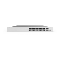
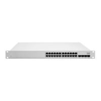
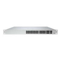
Details the physical specifications of the MS355 series switches, including port counts and power input.
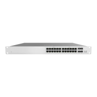
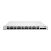
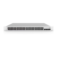
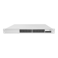
Illustrates the front panel layout for various MS355 switch models (MS355-24X, MS355-24X2, etc.).
Shows a diagram of the back panel of the MS355 series switches.
Explains the status indicators (LEDs) on the front panel of the MS355 series for operational feedback.
Describes back panel components like Restore button, Management Interface, Stack Ports, Fans, and Power Supplies.
Lists the items included in the MS355 switch package, including mounting kits and screws.
Outlines critical safety operations and precautions for installing and using the MS355 switch.
Guides on configuring the Meraki dashboard network before switch installation.
Explains dynamic IP address assignment via DHCP for Meraki switches, noting static requirements.
Describes how to configure static IP addresses using the switch's local web server.
Details initial steps for rack mounting, including installing cage nuts and rails.
Continues the process of attaching rack mount rails to the switch and rack.
Covers attaching the switch faceplate and securing it within the rack mount rails.
Details inserting the power supply unit and optional module installation.
Provides basic steps for troubleshooting connectivity issues, including reset procedures.
Details the warranty coverage periods for MS355 switches and accessories.
Guides on how to contact Meraki Support for installation issues or help.
Provides guidelines on equipment usage, disposal, storage, and transportation.
This document serves as an installation guide for the Cisco Meraki MS355 series switches, providing comprehensive instructions for setup, configuration, and basic troubleshooting. It is designed to assist users in deploying and managing their MS355 series switches effectively within a network environment.
The MS355 series switches are designed for robust network connectivity, offering a range of features that facilitate efficient data transfer and network management. These switches are capable of being connected in a physical stack using dedicated stacking ports and cables, allowing for scalable network expansion and simplified management of multiple devices as a single logical unit. This stacking capability enhances network resilience and streamlines configuration tasks across the stack.
For initial setup, the guide recommends a pre-installation preparation phase, which includes configuring the dashboard network. Users are instructed to log in to the Meraki dashboard, either creating a new account or finding an existing network, and then adding their switches to this network. This involves providing the Meraki order number or the serial number of each switch, along with an Enterprise license key. Once added, the switches can be virtually placed on a map or floor plan within the dashboard, aiding in physical deployment planning.
Before physical mounting, it is crucial to check and set the firmware. The switch should be connected to power and a wired internet connection. Upon powering on, the power LED will initially glow solid orange. If a firmware upgrade is required, the LED will blink white until the upgrade is complete, at which point it will turn solid white. This process ensures the switch operates with the latest software for optimal performance.
Network configuration involves checking and configuring upstream firewall settings. If a firewall is present, it must be configured to allow outgoing connections on specific ports to particular IP addresses, details of which can be found on the firewall configuration page in the Meraki dashboard.
Assigning an IP address is another critical step. All switches require routable IP addresses, which can be assigned dynamically via DHCP or statically. For dynamic assignment, it is recommended to configure the DHCP server to assign a static IP address for each Meraki switch's MAC address, especially for features like 802.1X authentication that rely on static IPs. For static assignment, users can connect a client machine to the switch, access its built-in web server via http://my.meraki.com or http://1.1.1.100, and configure the static IP address, net mask, gateway IP address, and DNS servers through the "Uplink Configuration" tab. The default login for this interface is the switch's serial number with no password.
The physical installation process is detailed with step-by-step instructions. It begins with installing mounting cage nuts in the rack where the switch will be housed. Next, the rack mount rails are separated, and the rack mount rail channel is installed onto the rack. The rack mount rail is then attached to the sides of the switch, and the entire assembly is inserted into the rack mount rail channel. Finally, the switch face plate is attached to the cage nuts on the rack, and the rack mount rail is secured to the rack mount rail channel. After securing the switch, the power supply unit is inserted into the back of the switch and connected to power. Optional SFP+, QSFP+, or QSFP28 units can be installed as needed, depending on the specific model and compatibility requirements.
Maintenance features primarily focus on basic troubleshooting and device restoration. The guide outlines steps for troubleshooting basic connectivity issues, such as resetting the switch. A brief, momentary press of the RESTORE button on the back panel will delete a downloaded configuration and reboot the device. Pressing and holding the RESTORE button for more than 10 seconds will force the unit into a full factory restore. Other troubleshooting tips include switching cables or testing the cable on another device. For more complex hardware issues, users are directed to contact Cisco Meraki support through the dashboard's "Help" option, where they can open an email case or call for assistance.
The document also provides information on warranty coverage periods for the MS355 series switches and their accessories. It clarifies that equipment is intended for use in restricted access locations and should only be installed and operated by trained service personnel. The equipment is designed for industrial and commercial activities, not domestic use, and is meant for operation without constant maintenance personnel presence. Installation and maintenance should be performed by specialists with appropriate qualifications.
Disposal of the technical device at the end of its service life must comply with all state regulations and laws, emphasizing that it should not be discarded with household waste. The equipment should be stored in its original packaging in a room protected from atmospheric precipitation, adhering to specified permissible temperature and humidity ranges during storage. Transportation should also be carried out in the original packaging, in covered vehicles, and in compliance with the permissible temperature and humidity ranges established for storage.
In summary, the Cisco Meraki MS355 series switches are designed for robust, scalable, and manageable network infrastructure. The installation guide provides a clear roadmap from initial setup and configuration through physical installation and basic troubleshooting, ensuring users can effectively deploy and maintain their network devices.
| Model | MS355 Series |
|---|---|
| Series | MS355 |
| Port Count | 48 |
| Gigabit Ethernet Ports | 48 |
| Uplink Ports | 4 |
| SFP+ Uplink Ports | 4 |
| Power over Ethernet (PoE) | Yes |
| Maximum PoE Budget | 740W |
| Switching Capacity | 176 Gbps |
| Management | Cloud-managed |
| Layer | Layer 2/3 |
| Operating Temperature | 32°F to 104°F (0°C to 40°C) |