Do you have a question about the Cisco Meraki MS120-48LP and is the answer not in the manual?
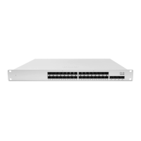
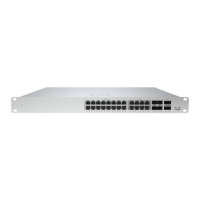
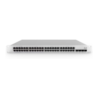
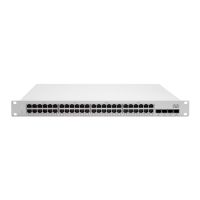
Details the physical specifications for MS120 series switches, including port counts and interface types.
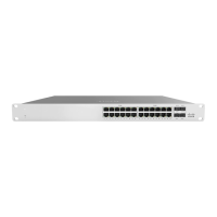
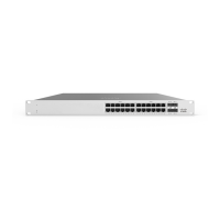
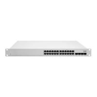
Illustrates the front panel layout of the MS120-24 and MS120-48 series switches.
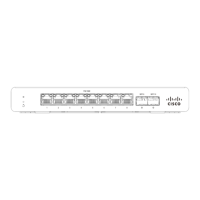
Shows the back panel of the MS120 Series switch, depicting ports and power connectors.
Overview of steps to add a switch to your Meraki network via the dashboard.
The Cisco Meraki MS120 Series is a line of Layer-2 gigabit Ethernet switches designed for network installations. This guide provides comprehensive instructions for the installation, configuration, and basic troubleshooting of these switches, ensuring optimal performance and connectivity within a network environment.
The MS120 Series switches are primarily designed to provide reliable Layer-2 network connectivity. They come in various models, offering different port counts and Power over Ethernet (PoE) capabilities to suit diverse network requirements. The switches are integrated with the Meraki cloud, allowing for centralized management and monitoring through the Meraki dashboard. This cloud integration simplifies deployment, configuration, and ongoing maintenance, making them suitable for both small and large-scale network infrastructures.
The switches facilitate the connection of various network devices, such as computers, access points, and IP cameras, providing gigabit Ethernet speeds for efficient data transfer. Models with PoE capabilities (MS120-24P, MS120-48LP, MS120-48FP) can power compatible devices directly over the Ethernet cable, reducing the need for separate power outlets and simplifying device deployment. The SFP (Small Form-Factor Pluggable) interfaces on all models allow for flexible uplink options, supporting fiber optic connections for longer distances or higher bandwidth requirements.
The MS120 Series switches are designed for ease of use and streamlined network management. Upon initial power-up, the switches automatically attempt to connect to the Meraki cloud. The Power LED provides visual feedback on the switch's status: solid orange indicates an inability to connect to the Meraki cloud, flashing white signifies a firmware upgrade in progress, and solid white confirms that the switch is fully operational and connected to the Meraki cloud. If the LED is off, it indicates that the switch does not have power.
For network configuration, the switches support both dynamic IP assignment via DHCP and static IP assignment. For dynamic assignment, it is recommended to configure the DHCP server to assign a static IP address for each Meraki switch's MAC address, which is crucial for features like 802.1X authentication. Static IP assignment can be performed through the switch's local web server, accessible via a wired connection and a web browser. Users can navigate to http://my.meraki.com or http://1.1.1.100 to access the "Uplink Configuration" tab. The default login credential is the switch's serial number without a password. This interface allows for the configuration of static IP address, netmask, gateway IP address, and DNS servers.
The switch ports also feature LED indicators. An off LED on a switch port means no link is detected, while a solid green LED indicates a 1 Gbps link. Flashing orange on RJ45 ports signifies activity. A dedicated Management Interface LED, when green, indicates a connected status, providing easy access to the local status page.
The Meraki dashboard plays a central role in managing these switches. After logging in, users can add switches to their network using the Meraki order number or the serial number found on the unit, along with the Enterprise license key. The dashboard allows for a visual representation of the network, enabling users to place switches on a map or floor plan, facilitating logical organization and monitoring.
The MS120 Series switches incorporate several features to aid in maintenance and troubleshooting. A Factory Reset Button is available on the front panel. A brief, momentary press of this button will delete a downloaded configuration and reboot the switch. Pressing and holding the button for more than 10 seconds will force the unit into a full factory restore, deleting all configuration information and restoring it to its original factory settings. This feature is invaluable for resolving configuration issues or preparing the switch for redeployment.
Before mounting the switch, it is recommended to facilitate a firmware upgrade to ensure optimal performance. The switch will automatically begin blinking white during an upgrade and turn solid white once complete. Users should allow a few minutes for this process, depending on internet connection speed.
Troubleshooting basic connectivity issues can be done by resetting the switch, performing a factory reset, or trying different cables. If issues persist, the Meraki documentation website provides additional troubleshooting tips, and users can contact Cisco Meraki support through the dashboard's "Help" option.
The switches are designed for 1U rack mounting, and the rack mount kit includes various screws and cage nuts for different rack types (US 12-24, INTL M5, INTL M6), along with mounting washers. Proper installation in a restricted access location by trained service personnel is emphasized, ensuring safety and compliance. Adequate airflow around the device is also crucial for optimal operation.
The product relies on the building's installation for short-circuit protection, with a recommended protective device rating of not greater than 15 A, 125 Vac, or 10A, 240 Vac. Only the provided power cables should be used to ensure regulatory compliance.
For hardware replacements under warranty, access to the original packaging, including the device serial number and order information, may be required. This ensures a smooth RMA process if a device fails and cannot be resolved through troubleshooting. The MS120 Series devices comply with Class B digital device limits, designed to provide reasonable protection against harmful interference in residential installations.
| Model | MS120-48LP |
|---|---|
| Port Count | 48 |
| Total Physical Ports | 52 |
| PoE Ports | 48 |
| PoE+ | Yes |
| Total PoE Budget | 370W |
| Uplink Ports | 4 x 1G SFP |
| Switching Capacity | 104 Gbps |
| Layer | Layer 2 |
| DRAM | 512 MB |
| Management | Cloud-managed |
| Power Supply | Internal |
| Operating Temperature | 0°C to 40°C (32°F to 104°F) |
| PoE Standard | 802.3af |
| MAC Address Table Size | 16, 000 |
| Form Factor | Rack mountable |