EasyManua.ls Logo

Cisco MERAKI MS425 Series

Cisco MERAKI MS425 Series
14 pages
To Next Page IconTo Next Page
Loading...
MS425 Series Installation Guide
About this Guide
This guide provides instruction on how to install and configure your MS425 series switch. This guide also provides mounting instructions and limited
troubleshooting procedures. For more switch installation guides, refer to the switch installation guides section on our documentation website.
Models
Model number Description
MS425-16
Layer-3 16-port 10GbE SFP+ aggregation switch with two 40GbE QSFP ports and 1 management interface, hot-swappable
power supplies / fans
MS425-32
Layer-3 32-port 10GbE SFP+ aggregation switch with two 40GbE QSFP ports and 1 management interface, hot-swappable
power supplies / fans
Product Overview
Physical Specifications
MS425-16 MS425-32
10GbE SFP+ 16 32
40GbE QSFP+ uplink/stacking ports 2 2
Dedicated Mgmt Interface 1 1
Hot Swap Power Supply Yes, Dual Yes, Dual
Hot Swap Fans Yes, 3x Yes, 3x
Power Input
100 - 240 VAC, 47-63 Hz
Power Consumption
98-136W 98-136W
Operating Temperature
32°F - 104 °F
0°C - 40 °C
32°F - 104 °F
0°C - 40 °C
1
Question and Answer IconNeed help?

Do you have a question about the Cisco MERAKI MS425 Series and is the answer not in the manual?

Cisco MERAKI MS425 Series Specifications

General IconGeneral
Stacking Ports2 x 40G QSFP+
Layer SupportLayer 3
VLAN SupportYes, up to 4094 VLANs
ACL SupportYes
QoS SupportYes
PoE SupportNo
Operating Temperature32°F to 104°F (0°C to 40°C)
Operating Humidity5% to 95% non-condensing
ModelMS425-16, MS425-32
Forwarding Rate476 Mpps
Ports16 x 10G SFP+
ManagementManaged via the Meraki cloud
StackingYes

Summary

About the Installation Guide

MS425 Series Models

Product Overview

Physical Specifications

Details physical attributes including port count, power input, and operating temperature ranges.

Product View and Features

Front Panel View

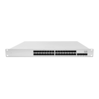
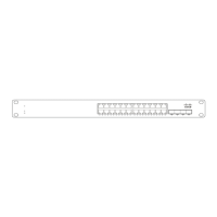
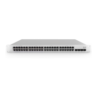
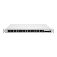
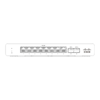
Visual representation of the front panel of MS425 series switches, showing ports and indicators.

Ports and Status Indicators

Front Panel Status LEDs

Explains the meaning of status LEDs on the front panel of the switch for operational feedback.

Factory Reset Button Functionality

Back Panel Status Indicators

Package Contents

Safety and Warnings

Pre-installation Preparation

Configure Dashboard Network

Steps to set up the Meraki dashboard network and add switches before on-site installation.

Check and Set Firmware

Recommended procedure for updating switch firmware before mounting for optimal performance.

Upstream Firewall Settings

Assigning IP Addresses

Static IP via DHCP Reservations

Method to reserve IP addresses for switches by configuring a DHCP server's reservations.

Installation Instructions

Mounting Hardware

Details about the rack mount kit and required clearances for proper installation and airflow.

Bringing your Stack Online

Steps to connect switches and configure ports for stacking to enable configuration synchronization.

Basic Troubleshooting

Warranty Coverage

Support and Additional Information

Related product manuals