EasyManua.ls Logo

Cisco Meraki MS210 Series

Cisco Meraki MS210 Series
15 pages
To Next Page IconTo Next Page
Loading...
MS210 Series Installation Guide
About this Guide
This guide provides instruction on how to install and configure your MS210 series switch. This guide also provides
mounting instructions and limited troubleshooting procedures. For more switch installation guides, refer to the
switch installation guides section on our documentation website.
Model number Description
MS210-24 Stackable Layer-2 24-port gigabit Ethernet switch with 4 SFP interfaces
MS21024P
Stackable Layer-2 24-port gigabit Ethernet 370W PoE switch with 4 SFP
interfaces
MS210-48 Stackable Layer-2 48-port gigabit Ethernet switch with 4 SFP interfaces
MS210-48LP
Stackable Layer-2 48-port gigabit Ethernet 370W PoE switch with 4 SFP
interfaces
MS210-48FP
Stackable Layer-2 48-port gigabit Ethernet 740W PoE switch with 4 SFP
interfaces
Product Overview
Physical Specifications
MS210-24 MS210-24P
MS210-48 MS210-48LP MS210-48FP
1
Question and Answer IconNeed help?

Do you have a question about the Cisco Meraki MS210 Series and is the answer not in the manual?

Cisco Meraki MS210 Series Specifications

General IconGeneral
LayerLayer 2
Cloud ManagementYes
Operating Temperature32°F to 104°F (0°C to 40°C)
Humidity5% to 95% non-condensing
Ports24 or 48 Gigabit Ethernet ports
Switching Capacity176 Gbps
Power over Ethernet (PoE)Available on PoE models
Maximum PoE Budget370W
ManagementManaged via Meraki Dashboard
VLAN SupportYes
MountingRack-mountable (1U)
Power SupplyInternal, 100-240V AC, 50-60 Hz

Summary

About this Guide

Product Overview

Physical Specifications

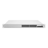
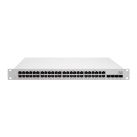
Details the physical attributes and specifications of MS210 series switches.

Product View and Physical Features

Front Panel

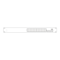
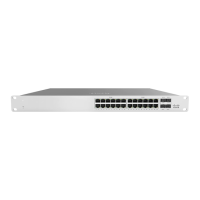
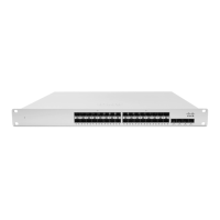
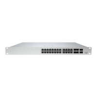
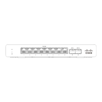
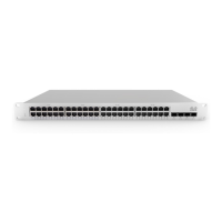
Illustrates the front panel layout and components of the MS210 series.

Back Panel

Displays the back panel layout and connections for the MS210 series.

Ports and Status Indicators

Explains the function of LEDs for network ports and device status.

Front Panel Components

Power

Describes the LED status and meaning for the power function on the front panel.

Restore

Details the function of the restore button on the front panel.

Switch Ports

Explains LED status and meaning for different link speeds on switch ports.

Back Panel Components

Management Interface

Describes the LED status and meaning for the management interface.

RPS2300 Redundant Power Supply (Optional)

Safety and Warnings

Pre-install Preparation

Configure your Dashboard Network

Provides steps for adding and configuring switches in the Meraki dashboard.

Check and Set Firmware

Recommends performing a firmware upgrade before switch installation.

Check and Configure Upstream Firewall Settings

Assigning an IP Address

Dynamic Assignment

Explains using DHCP to assign static IP addresses based on MAC addresses.

Static Assignment

Details manual static IP configuration via the switch's built-in web server.

Static IP via DHCP Reservations

Describes reserving IP addresses for switches using an upstream DHCP server.

Installation Instructions

Basic Troubleshooting

Reset the switch

Outlines basic troubleshooting steps, including resetting the switch.

Factory reset the switch by holding the factory reset button for 5 seconds

Provides instructions for performing a factory reset on the switch.

Try switching cables, or testing your cable on another device

Suggests troubleshooting network connectivity by testing cables and devices.

Bringing your Stack Online

Warranty

Support and Additional Information

Related product manuals