Do you have a question about the Cisco MS225-24P and is the answer not in the manual?
Includes mounting screws, cage nuts for US and INTL, and washers for rack installation.
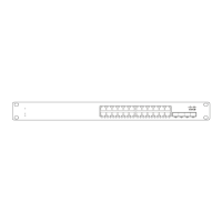
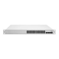
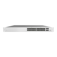
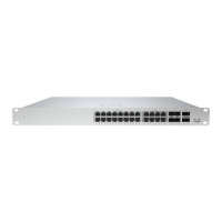
Diagram illustrating the front panel layout for the MS225-24 series switch.
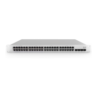
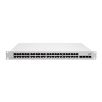
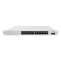
Diagram illustrating the front panel layout for the MS225-48 series switch.
Describes LED status meanings for the Power indicator (solid orange, flashing white, solid white, off).
Explains the function of the Restore button and its N/A LED status.
Details LED status for switch ports (off, solid orange, solid green) indicating link detection and speed.
Describes the green LED status for the Management Interface connection.
Details the green LED status for connected QSFP stacking cables and off status for no link.
Explains the N/A status for the 22-Pin RPS2300 connector for redundant power.
Lists supported Cisco part numbers and descriptions for RPS chassis, power supplies, and cables.
Information on cross-model stacking compatibility between MS210 and MS225 series switches.
Details on using the included rack mount kit for standard 1U racks and ensuring airflow.
Notes the availability of a mid-mount bracket for MS225 48 port models with 2-post racks.