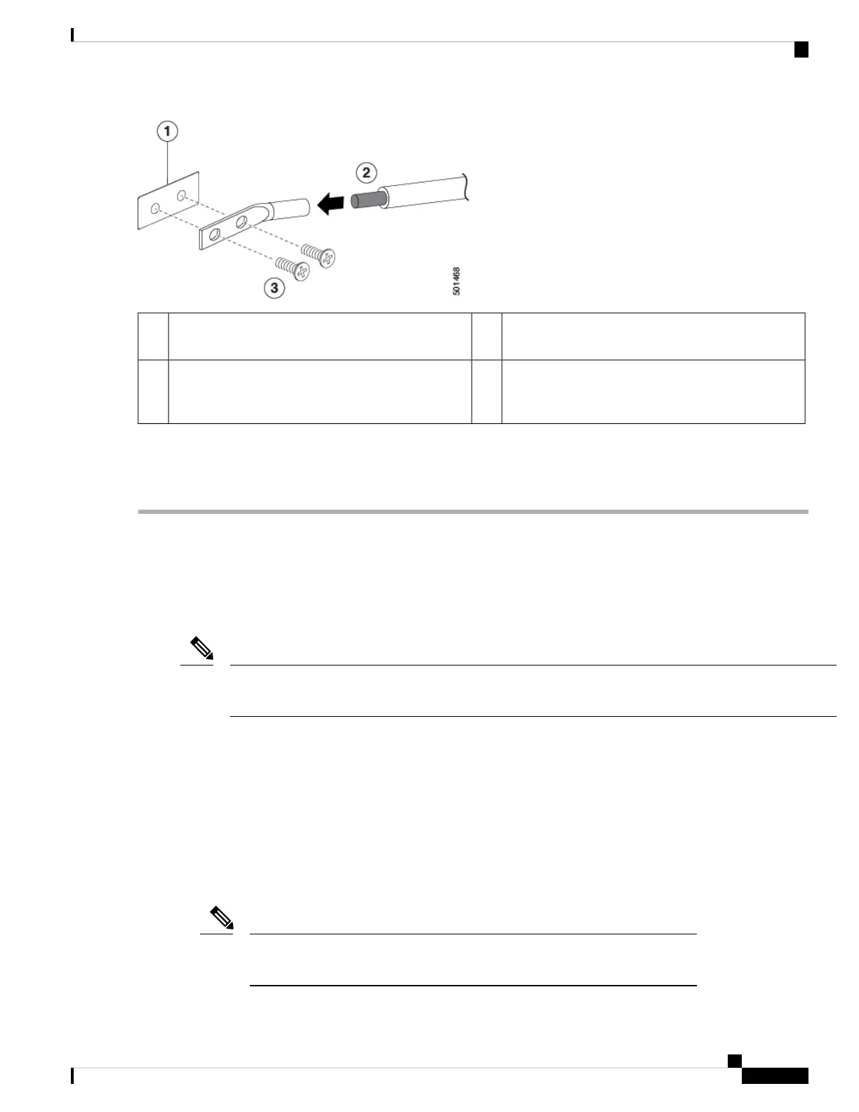
2 M4 screws are used to secure the grounding lug to
the chassis
3Chassis grounding pad1
Grounding cable, with 0.75 in. (19 mm) of insulation
that is stripped from one end, which is inserted into
the grounding lug and crimped in place
2
Step 3 Secure the grounding lug to the chassis grounding pad with two M4 screws, see the previous figure. Tighten the screws
to 11 to 15 in-lb (1.24 to 1.69 N·m) of torque.
Step 4 Prepare the other end of the grounding wire and connect it to the facility ground.
Starting the Switch
You start the switch by connecting it to its dedicated power source. If you need n+n redundancy, you must
connect each power supply in a switch to a different power source.
This equipment is designed to boot up in less than 30 minutes, dependent on its neighboring devices being
fully up and running.
Note
Before you begin
• The switch must be installed and secured to a rack or cabinet.
• The switch must be adequately grounded.
• The rack must be close enough to the dedicated power source so that you can connect the switch to the
power source by using a designated power cables.
• You have the designated power cables for the power supplies that you are connecting to the dedicated
power sources.
Depending on the outlet receptacle on your AC power distribution unit, you might
need an optional jumper power cord to connect the switch to your outlet receptacle.
Note
Cisco Nexus 93180YC-FX3 ACI-Mode Switch Hardware Installation Guide
29
Installing the Switch Chassis
Starting the Switch
 Loading...