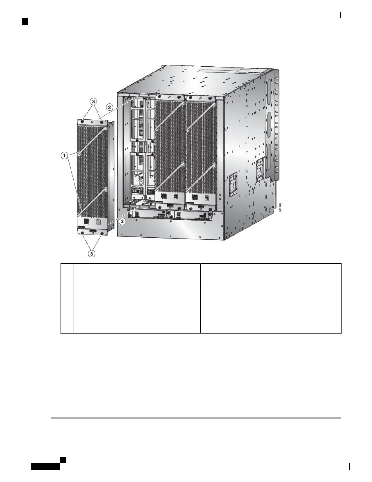
Figure 66: Install Fan Tray in Chassis
Screw in four captive screws and tighten each screw
to 8 in-lb (0.9 N·m) of torque.
3Hold the two fan tray handles with your two hands.1
Position the back of the fan tray to the open fan tray
slot. The pins on the top and bottom of the fan tray
should align to holes in the chassis and the two sets
of rails on the top of the fan tray should align to two
sets of tracks on the top of the open slot. Slide the
fan tray all the way into the slot.
2
b) Position the fan tray with its rear (the side with the electrical connectors) at the opening for the fan tray slot in the
chassis.
c) Align the two tracks on the top of the fan tray with the two sets of rails at the top of the open fan tray slot in the
chassis.
d) Slide the fan tray all the way into the slot until the front of the fan tray touches the chassis.
Make sure that the four captive screws on the front of the fan tray align with the four screw holes in the chassis.
e) Screw in the four captive screws to secure the fan tray to the chassis. Tighten the screws to 8 in-lb (0.9 N·m) of torque.
f) Verify that the fan tray and fabric card STATUS LEDs (on the fan tray) turn on and become green.
Hardware Installation Guide for Cisco NCS 5500 Series Modular Routers
116
Replace Chassis Components
Install a Fabric Card