The lever should click when you rotate it all the way to the front of the power supply. Be sure that the power supply
is fully inserted into the slot (the front of the power supply should be even with the surface of the chassis) and securely
in place.
Step 5 Connect the power cables to the power supply as follows:
a) Verify that the circuit breakers for both input lines from the DC power source are turned off.
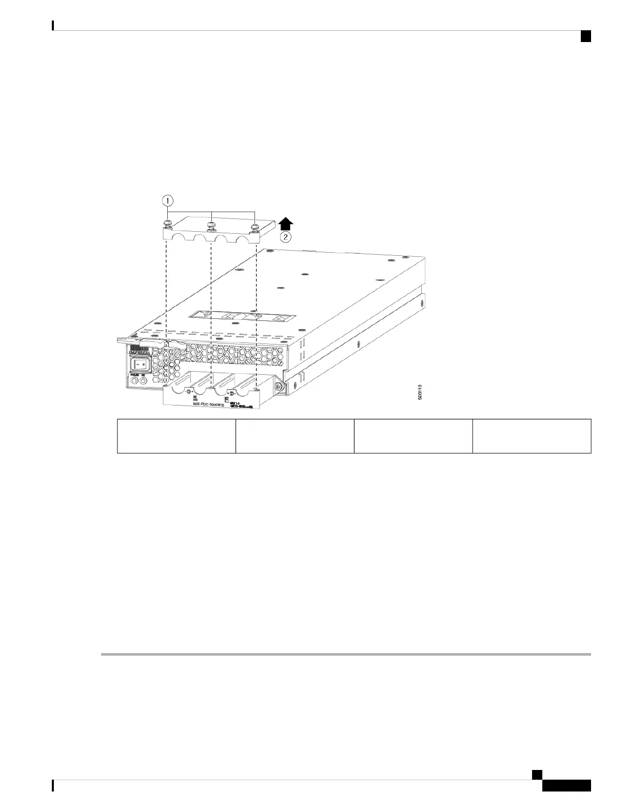
b) Use a torque screwdriver to unscrew three screws on the cover for the terminal box that is located on the front of the
power supply and lift off the cover as shown in the following figure.
Remove the cover.2Remove 3 screws from the
safety cover.
1
c) Remove the two nuts from each terminal post in each slot of the terminal box.
d) Place each of the lugs for the two positive cables on the terminal posts for the positive slots (two middle slots) of the
terminal box and fasten each lug using two nuts tightened to 40 in-lb (4.5 N·m) of torque.
e) Place each of the lugs for the two negative cables on the terminal posts for the negative slots (two side slots) of the
terminal box and fasten each lug using two nuts tightened to 40 in-lb (4.5 N·m) of torque.
f) Replace the safety cover on the terminal box and fasten it in place using its three screws.
Step 6 Power up the power supply as follows:
a) Turn on the power source circuit breaker for both input lines.
Verify that the Input 1 (IN1) and Input 2 (IN2) LEDs light up on the power supply.
b) Turn the power switch on the power supply to ON (labeled 1 on the power supply).
The LEDs should flash and then the OK LED should turn on (green) in addition to the Input LEDs.
Hardware Installation Guide for Cisco NCS 5500 Series Modular Routers
123
Replace Chassis Components
Replace DC Power Supply