d) Slide the handle on the middle of the power supply release lever towards the end of the module and rotate the lever
away from the front of the power supply while pushing the power supply all the way into the chassis (see the following
figure).
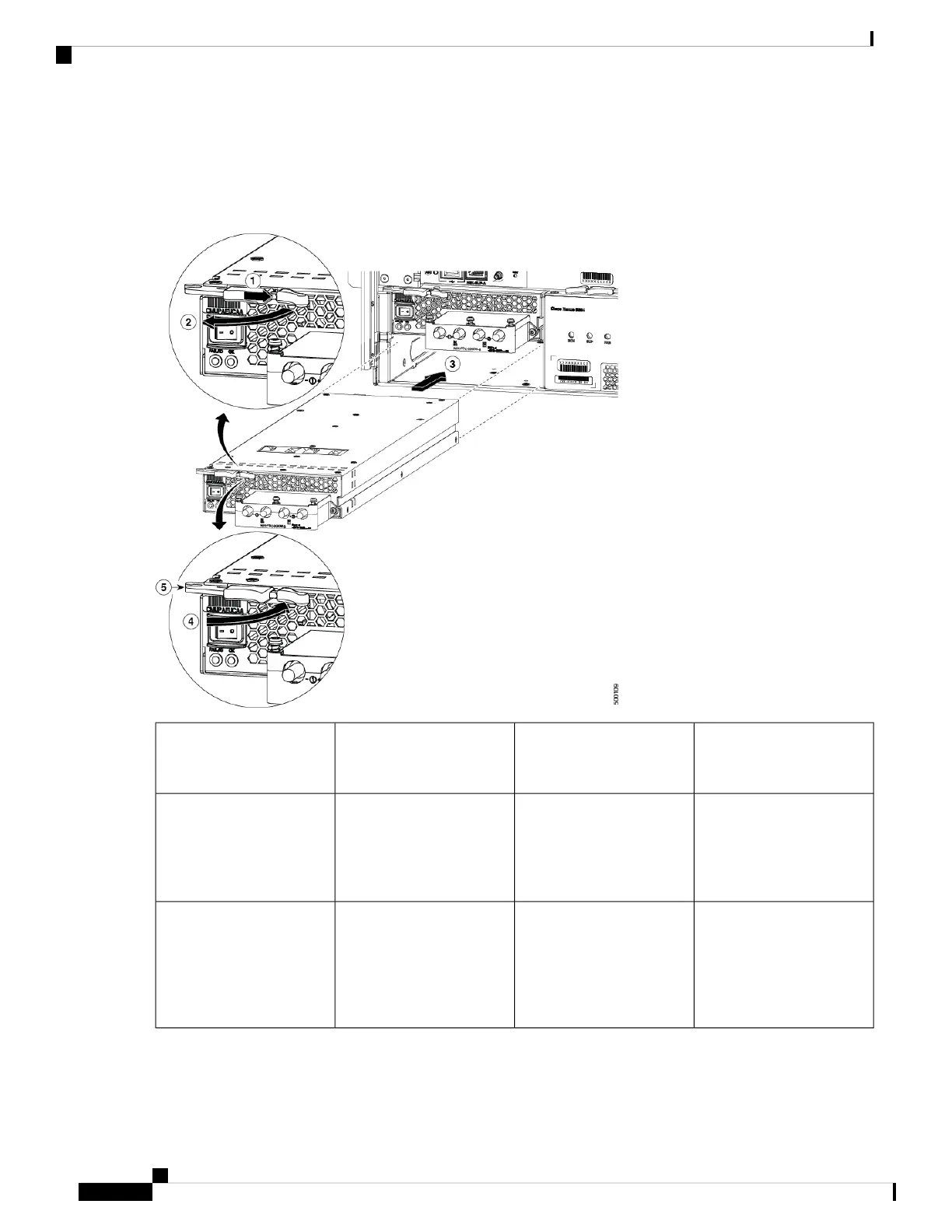
Figure 69: Install DC Power Supply
Rotate the lever towards the
front of the module.
4Slide and hold the middle
handle next to the outer
handle.
1
Make sure that the other end
of the lever grabs the front
of the chassis to push the
module onto the connectors
inside the slot.
5Fully rotate the release lever
away from the front of the
module.
2
Slide the power supply into
the open power supply slot
in the chassis until it stops
with the front of the module
about 0.25 inches (0.6 cm)
in front of the chassis.
3
e) Rotate the ejector lever toward the front of the power supply and be sure that the other end of the lever locks into the
chassis.
Hardware Installation Guide for Cisco NCS 5500 Series Modular Routers
122
Replace Chassis Components
Replace DC Power Supply