c) Secure the bottom portion of the assembly to the chassis using two M4 x 12 MM flat-head Phillips screws in each
of the two angled brackets on the assembly. Tighten each screw to 11.5 to 15 in-lb (1.3 to 1.7 N·m) of torque.
d) Repeat Steps 2a and 2c to attach the other side filter frame assembly to the mounting bracket on the opposite side of
the chassis.
Step 3 Attach the two air filters to the side filter frames as follows:
a) Remove an air filter from its packaging and position it on the side frames.
NCS 5504: Ensure that its 9 holes align with 9 screw holes in the side brush filter frame.
NCS 5508: Ensure that its 10 holes align with 10 screw holes in the side brush filter frame.
NCS 5516: Ensure that its 14 holes align with 14 screw holes in the side brush filter frame.
b) Fasten the air filter to the side brush filter assembly.
NCS 5504: Use 9 M3 x 12 mm screws.
NCS 5508: Use 10 M3 x 12 mm screws.
NCS 5516: Use 14 M3 x 12 mm screws.
c) Tighten the M3 screws to 5 to 7 in-lb (0.56 to 0.79 N.m) of torque.
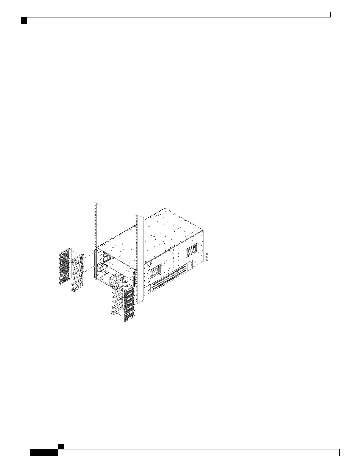
Figure 23: Attach Side Filter Assembly to NCS 5504 Chassis
Hardware Installation Guide for Cisco NCS 5500 Series Modular Routers
54
Install the Chassis
(Optional) Install Air Filter, Cable Management Bracket, or Door Kit on a Chassis