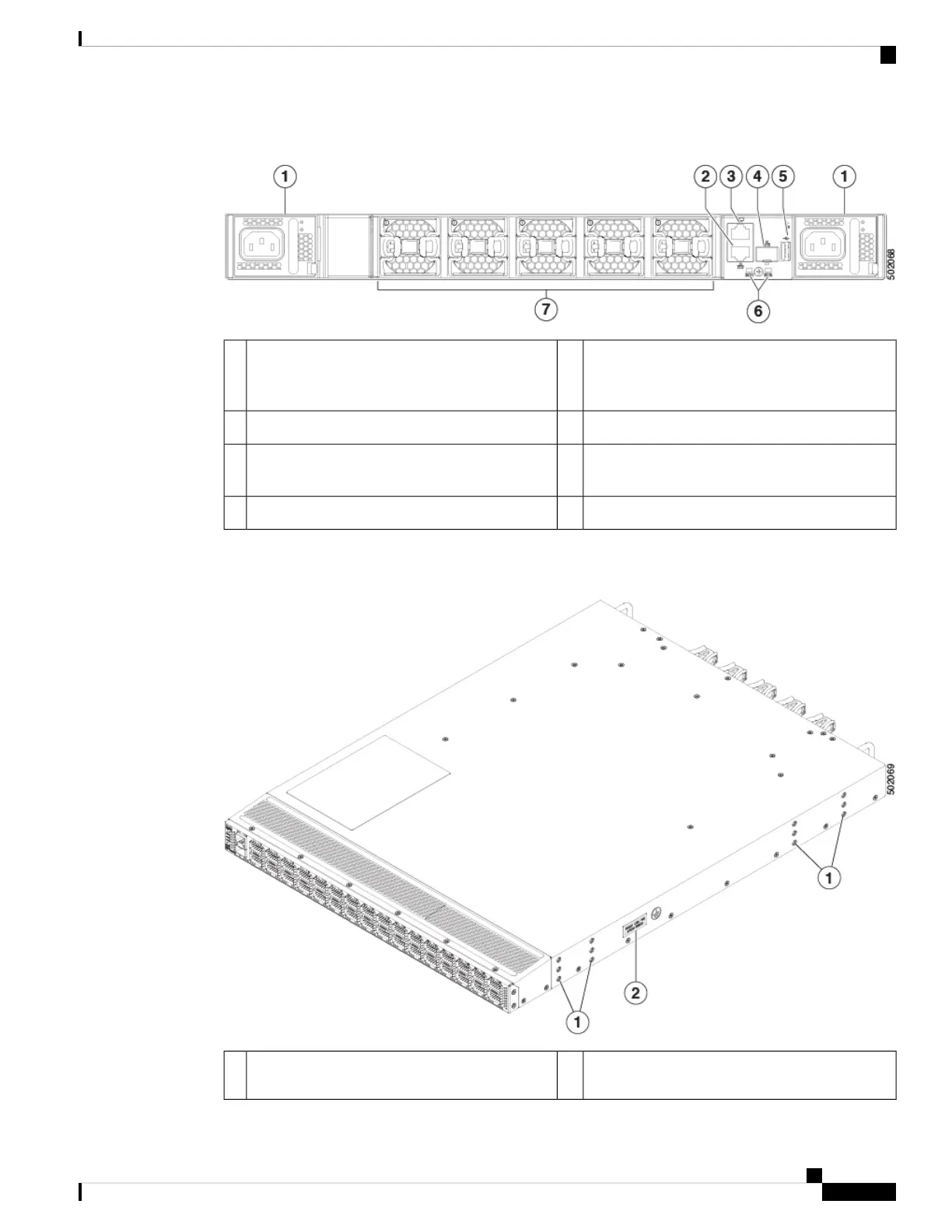
Figure 2: Power Supply Side View of the Cisco Nexus 9332C Switch
USB port5Power supply (2), one is for operations and one
is for redundancy. Power supply slot 1 on the left
and slot 2 on the right.
1
Chassis LEDs (Beacon [BCN] and Status [STS])6Management port (RJ-45)2
Fan modules (5) with fan slot 1 on the left and fan
slot 5 on the right
7Console port (RS232)3
Management port (SFP)4
The following figure shows the hardware features seen from the side of the chassis.
Figure 3: Side View of the Cisco Nexus 9332C Switch
Screw holes (2) for attaching grounding lug2Screw holes (6) for attaching rack mounting
brackets
1
Cisco Nexus 9332C ACI-Mode Switch Hardware Installation Guide
3
Overview
Overview
 Loading...