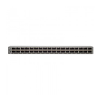
The following figure shows the switch features on the power supply side of the chassis.
Management port (RJ45)4Power supply modules (1 or 2) (AC
power supplies shown) with slots
numbered 1 (left) and 2 (right)
1
Management port (SFP)5Fan modules (6) with slots
numbered from 1 (left) to 6 (right)
2
USB port6Console port3
The following figure shows the side of the chassis.
Grounding pad2Screw holes for mounting brackets1
The fan and power supply modules are field replaceable. You can replace one fan module or one power supply
module during operations so long as the other modules are installed and operating. If you have only one power
supply installed, you can install the replacement power supply in the open slot before removing the original
power supply.
All fan and power supply modules must have the same direction of airflow. Otherwise, the switch can overheat
and shut down.
Note
If the switch has port-side intake airflow (burgundy coloring for fan modules), you must locate the ports in
the cold aisle. If the switch has port-side exhaust airflow (blue coloring for fan modules), you must locate the
ports in the hot aisle. If you locate the air intake in a hot aisle, the switch can overheat and shut down.
Caution
Cisco Nexus 9332D-GX2B ACI-Mode Switch Hardware Installation Guide
3
Overview
Overview
 Loading...