Each fan module has two rotors. The switch can function normally if one rotor
inside the any one fan module fails. In case of more than one rotor failure, the
switch will issue a warning and power down in 2 minute.
Note
• Power supply modules (two—One for operations and one for redundancy [1+1]) with the following
choices:
• 750-W port-side exhaust AC power supply with blue coloring (NXA-PAC-750W-PE)
• 750-W port-side intake AC power supply with burgundy coloring (NXA-PAC-750W-PI)
• 1100-W port-side exhaust AC power supply with blue coloring (NXA-PAC-1100W-PE)
• 1100-W port-side intake AC power supply with burgundy coloring (NXA-PAC-1100W-PI)
• 1100-W port-side exhaust DC power supply with blue coloring (NXA-PDC-1100W-PE2)
• 1100-W port-side intake DC power supply with burgundy coloring (NXA-PDC-1100W-PI2)
All fan modules and power supplies must use the same airflow direction.
Note
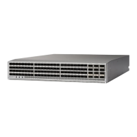
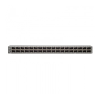
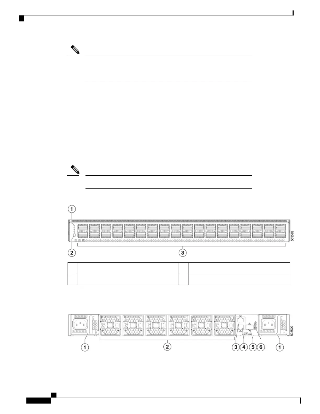
The following figure shows the switch features on the port side of the chassis.
36 40/100-Gigabit QSFP28 ports3LEDs1
Lane select button2
To determine which transceivers, adapters, and cables are support this switch, see the Cisco Transceiver
Modules Compatibility Information document.
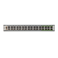
The following figure shows the switch features on the power supply side of the chassis.
Cisco Nexus 9336C-FX2-E ACI-Mode Switch Hardware Installation Guide
2
Overview
Overview