Send document comments to ucs-docfeedback@cisco.com
24
Cisco UCS B200 Blade Server Installation and Service Note
OL-22473-02
Removing a Blade Server Cover
Memory Arrangement
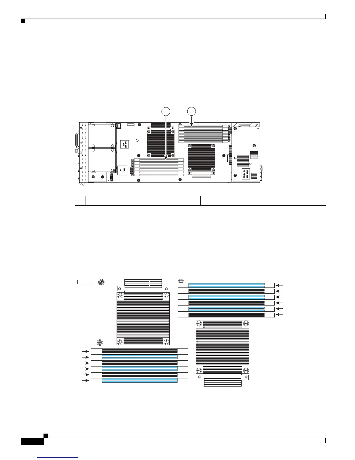
The blade server contains 12 DIMM slots—six for each CPU. Each set of six DIMM slots is arranged
into three channels, where each channel has 2 DIMMs (see Figure 13 and Figure 14).
Figure 13 Memory Slots within the Blade Server
Each channel is identified by a letter—A, B, C for CPU1, and D, E, F for CPU 2. Each DIMM slot is
identified by a number, either 1 or 2. Note that each DIMM slot 1 is blue, while each slot 2 is black.
Figure 14 shows how DIMMs and channels are physically laid out on the blade server. The DIMM slots
in the upper right are associated with the right CPU, while the DIMM slots in the lower left are associated
with the left CPU.
Figure 14 Physical Representation of DIMMs and Channels
1 Channels D-F for CPU 2 2 Channels A-C for CPU 1
194240
1
2
F1
F2
E1
E2
D1
D2
A2
A1
B2
B1
C2
C1
194241
Battery