Cisco UCS B22 M3 Blade Server
34
SUPPLEMENTAL MATERIAL
DIMM and CPU Layout
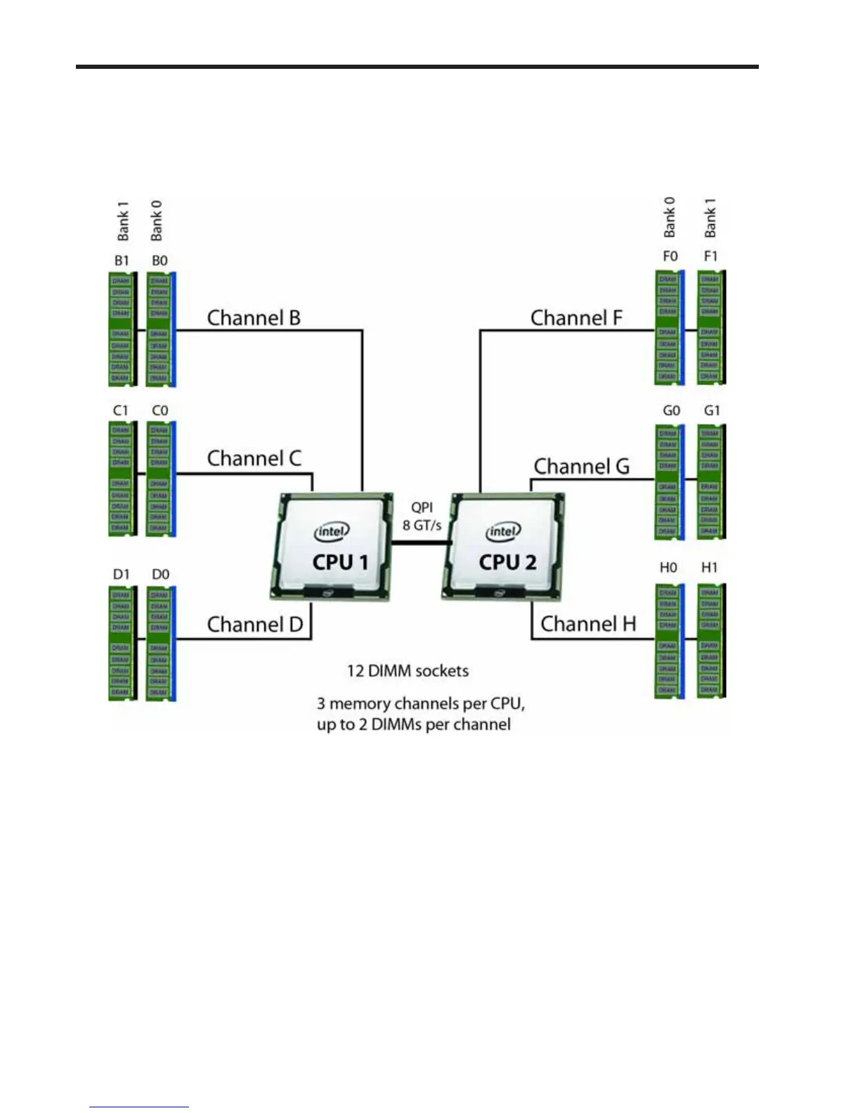
Memory is organized as shown in Figure 7.
Figure 7 UCS B22 M3 Memory Organization
Each CPU controls three memory channels, as follows:
■ CPU1: Channels B, C, and D
— Bank 0 - B0, C0, and D0 (blue DIMM slots)
— Bank 1 - B1, C1, and D1 (black DIMM slots)
■ CPU2: Channels F, G, and H
— Bank 0 - F0, G0, and H0 (blue DIMM slots)
— Bank 1 - F, G1, and H1 (black DIMM slots)
The DIMM and CPU physical layout is shown in Figure 8. The 6 DIMM slots at the left are controlled by CPU 1
and the 6 DIMM slots on the right are controlled by CPU 2.