D-7
Cisco UCS C240 M4 Server Installation and Service Guide
OL-32474-01
Appendix D GPU Card Installation
Step 8 Move the six fan modules from the old fan cage to the new fan cage that you just installed:
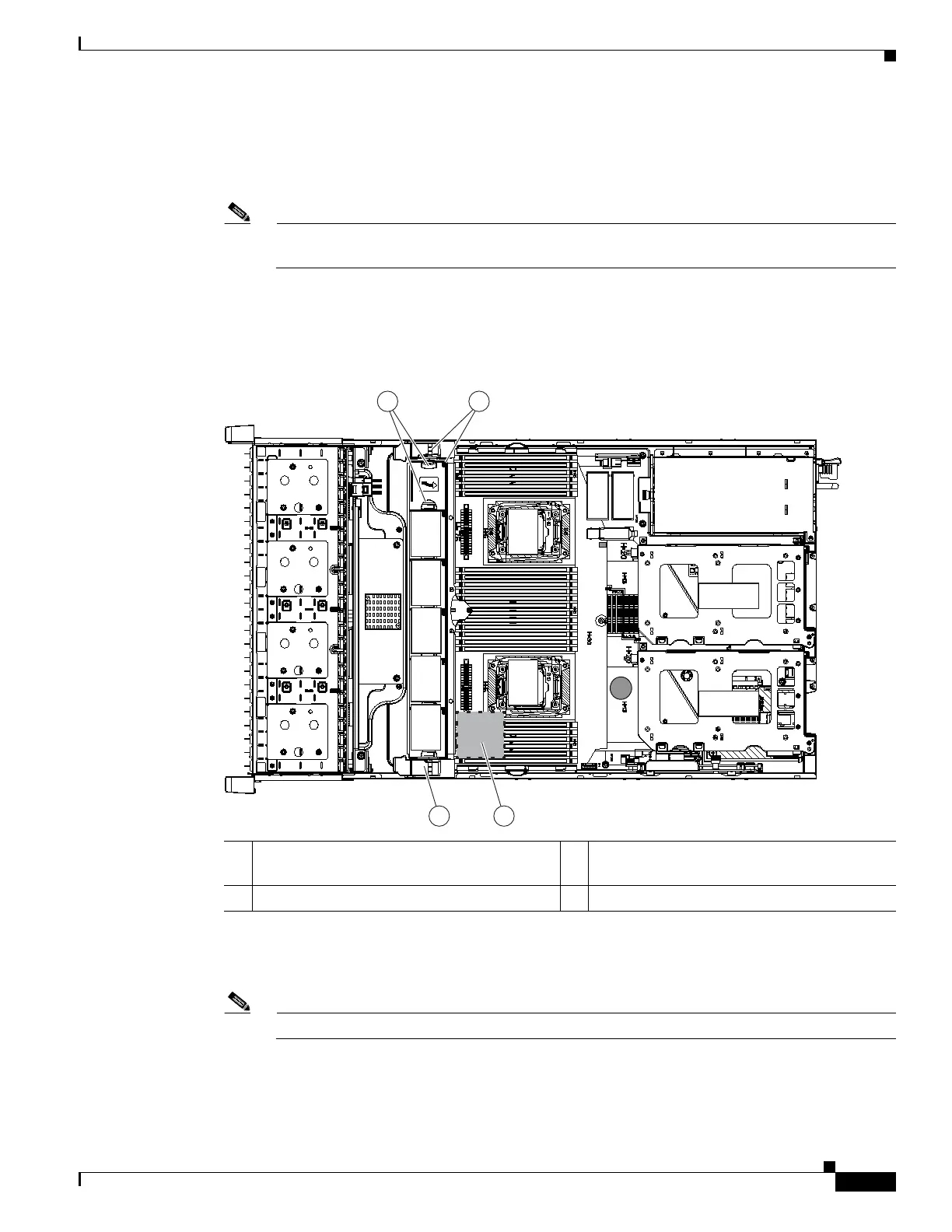
a. Pinch the two finger latches on each fan module together, then lift up on the module to remove it
from the cage (see Figure D-1).
b. Set the fan module in an open slot in the new fan cage, aligning the connector on the bottom of the
fan module with the connector on the motherboard.
Note The arrow label on the top of the fan module, which indicates the direction of airflow, should
point toward the rear of the server.
c. Press down gently on the fan module until the latch clicks and locks in place.
d. Repeat until you have moved all fan modules into the new fan cage.
Figure D-1 Fan Cage and Fan Modules
Step 9 Remove the existing heatsink from each CPU.
a. Use a Number 2 Phillips-head screwdriver to loosen the four captive screws that secure the heatsink.
Note Alternate loosening each screw evenly to avoid damaging the heatsink or CPU.
b. Lift the heatsink off of the CPU and set it aside.
Step 10 Use the heatsink cleaning kit that comes with the conversion kit to clean the existing thermal grease from
the top surface of each CPU.
1 Finger latches (on each fan module) 3 SuperCap power module position on
removable air baffle (air baffle not shown)
2 Fan cage plastic locking-levers
FAN 05
FAN 04
FAN 0 3
FAN 02
FAN 01
CPU 1
CPU 2
SD1
SD2
Riser 2
Riser 1
305091
1 2
2 3

 Loading...


