3-21
Cisco UCS C240 M4 Server Installation and Service Guide
OL-32474-01
Chapter 3 Maintaining the Server
Installing or Replacing Server Components
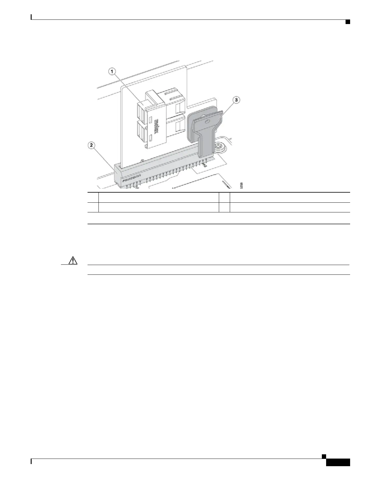
Figure 3-11 PCIe Interposer Board
Step 1 Power off the server as described in Shutting Down and Powering Off the Server, page 3-9.
Step 2 Slide the server out the front of the rack far enough so that you can remove the top cover. You might have
to detach cables from the rear panel to provide clearance.
Caution If you cannot safely view and access the component, remove the server from the rack.
Step 3 Remove the top cover as described in Removing and Replacing the Server Top Cover, page 3-10.
Step 4 Install a new PCIe interposer board:
a. Locate the PCIe interposer board socket on the motherboard (see Figure 3-12).
b. Pinch the securing clip on the board while you insert the board to the socket as shown in Figure 3-11.
c. Carefully push down to seat the board, then release the securing clip.
Step 5 Connect the two cables that come with the interposer board:
a. Connect the double-connector end of the cable to the interposer board (see Figure 3-11).
b. Route the cables to the front of the server using the recommended path through the chassis cable
guides as shown in Figure 3-12.
c. Connect the two ends of the cable to the PCIe connectors on the drive backplane.
Connect the cable labeled Port A to the Port A connector; connect the cable labeled Port B to the
Port B connector.
Step 6 Replace the top cover.
Step 7 Replace the server in the rack, replace cables, and then power on the server by pressing the Power button.
1 Connector for PCIe cable 3 Securing clip on interposer board
2 Motherboard socket

 Loading...


