EasyManuals Logo

Cisco VG202 User Manual

Cisco VG202
18 pages
To Next Page IconTo Next Page
To Previous Page IconTo Previous Page
Page #11 background imageLoading...
Page #11 background image
11
Procedure
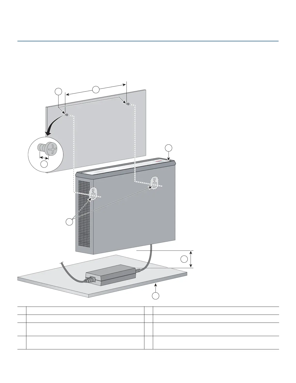
Step 1 Secure two screws 5 7/16 in (13.81 cm) apart into a wall and 5/32 in (0.40 cm) out from the wall.
Step 2 Hang the chassis on the screws as shown in Figure 7.
Step 3 Place the power supply on a horizontal surface.
Figure 7 Mounting the Cisco VG202, Cisco VG202XM, Cisco VG204, or Cisco VG204XM Voice Gateway Chassis on a Wall
1
Two number-six, 3/4-in. screws
2
Distance between the two screws (5 7/16 in. [13.81 cm])
3
Chassis
4
Mounting-screw slots
5
Maximum distance between the chassis and the power
supply (6 ft [1.8 m])
6
Horizontal surface on which to set the power supply
7
Distance between the screw and the wall
(1/8 in. [0.32 cm])
231985
1
5
6
4
2
7
3

Other manuals for Cisco VG202

Questions and Answers:

Question and Answer IconNeed help?

Do you have a question about the Cisco VG202 and is the answer not in the manual?

Cisco VG202 Specifications

General IconGeneral
Product TypeVoice Gateway
Voice Ports2 FXS ports
Network Interfaces1 x 10/100Base-TX
Protocols SupportedSIP
Operating Temperature32°F to 104°F (0°C to 40°C)
Relative Humidity10 - 90% (non-condensing)

Related product manuals