4
CT-S300 Service Manual
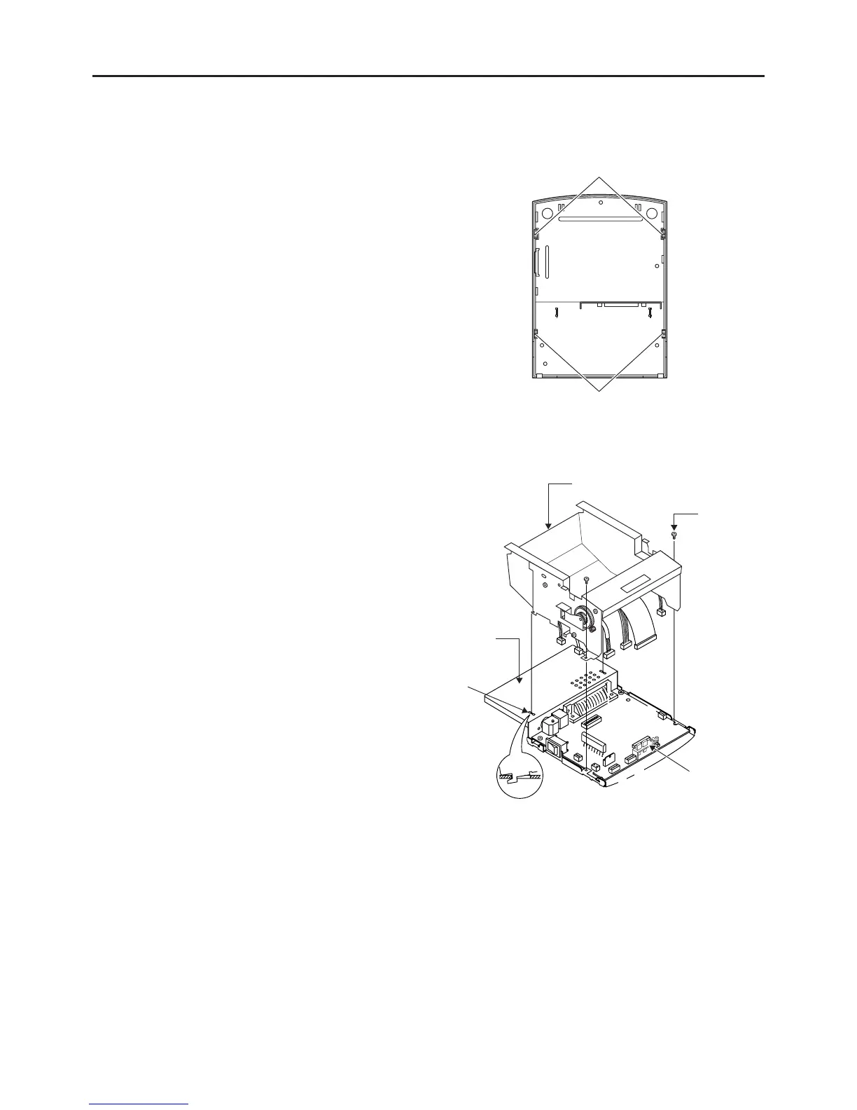
(2) Removing mechanism unit
• Remove the LED guide.
• Remove the two M3 × 8 (ST) screws.
• Remove the connectors and FFC from the control
board assembly.
• Remove the mechanism unit from the square hole
of the bottom chassis.
A
A
B
B
E
E
F
F
D
D
C
C
3.2 Disassembly Procedure
3.2.1 Overall Disassembly
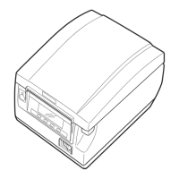
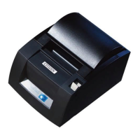
(1) Removing top cover
• Place the printer in vertical state.
• Open the paper cover using the cover open lever.
• Remove the printer chassis from the four “hooks”
at the bottom of the top cover.
* Pay attention not to break the “hook”.
Mechanism unit
Square hole
Bottom chassis
M3 × 8 (ST)
Hook
Hook
LED guide
 Loading...