5
CT-S300 Service Manual
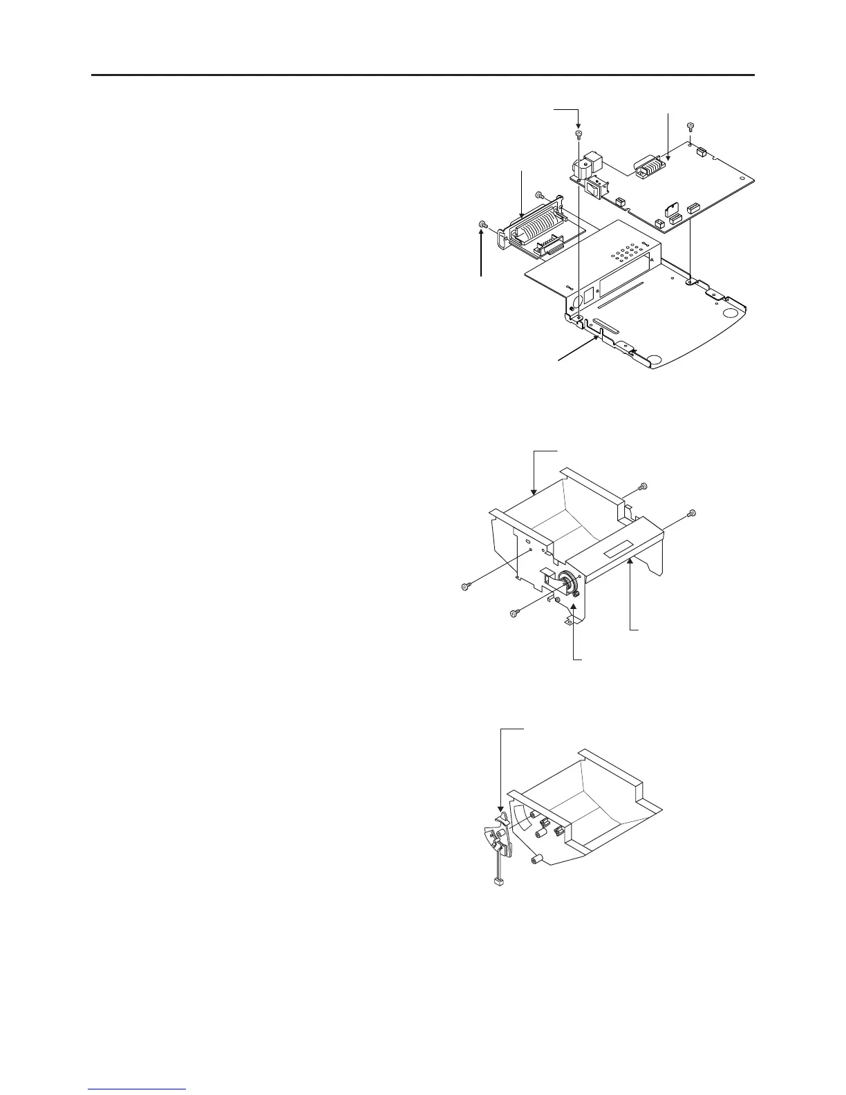
(3) Removing interface board assembly
• Remove the two M3 × 6 (ST) screws.
• Remove the interface board assembly.
(4) Removing control board assembly
• Remove the two M3 × 6 (ST) screws.
• While removing the power switch from the switch
guide, remove the control board assembly.
Bottom chassis
3.2.2 Disassembly of Mechanism Chassis Assembly
(1) Removing auto cutter
• Remove the two M3 × 6 (ST) screws from both
sides.
• Widen the main chassis a little, remove the four
guide bosses, and remove the auto cutter.
(2) Removing center frame
• Remove the two M3 × 8 tapping (ST) screws
from both sides.
• Widen the main chassis a little and remove the
center frame while removing the four guide
bosses.
(3) Removing paper near-end lever assembly
• Remove the assembly from the center frame.
Control board assembly
M3 × 6 (ST)
Interface board assembly
M3 × 6 (ST)
Switch guide
Paper near-end lever assembly
Center frame
M3 × 8 tapping
screws [ST]
M3 × 8 (ST)
Auto cutter
Main chassis
 Loading...