CT-S4000 Service Manual
5
1.2 Disassembly Procedure
1.2.1 Disassembly of Unit
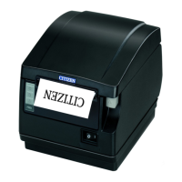
1. Removing SA IF PCB
・Remove two M3x6(ST) screws.
・Remove SA IF PCB.
(When reassembling, insert the connector correctly.)
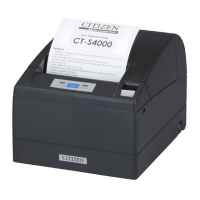
2. Removing CASE
・Open COVER and remove two M3x6(ST) screws.
・Remove FRAME, BOTTOM from the two hooks on the
front of CASE bottom, remove FRAME, BOTTOM from
two hooks on the right and left of the CASE, and lift
CASE for removal.
(Remove three connectors while lifting CASE.)
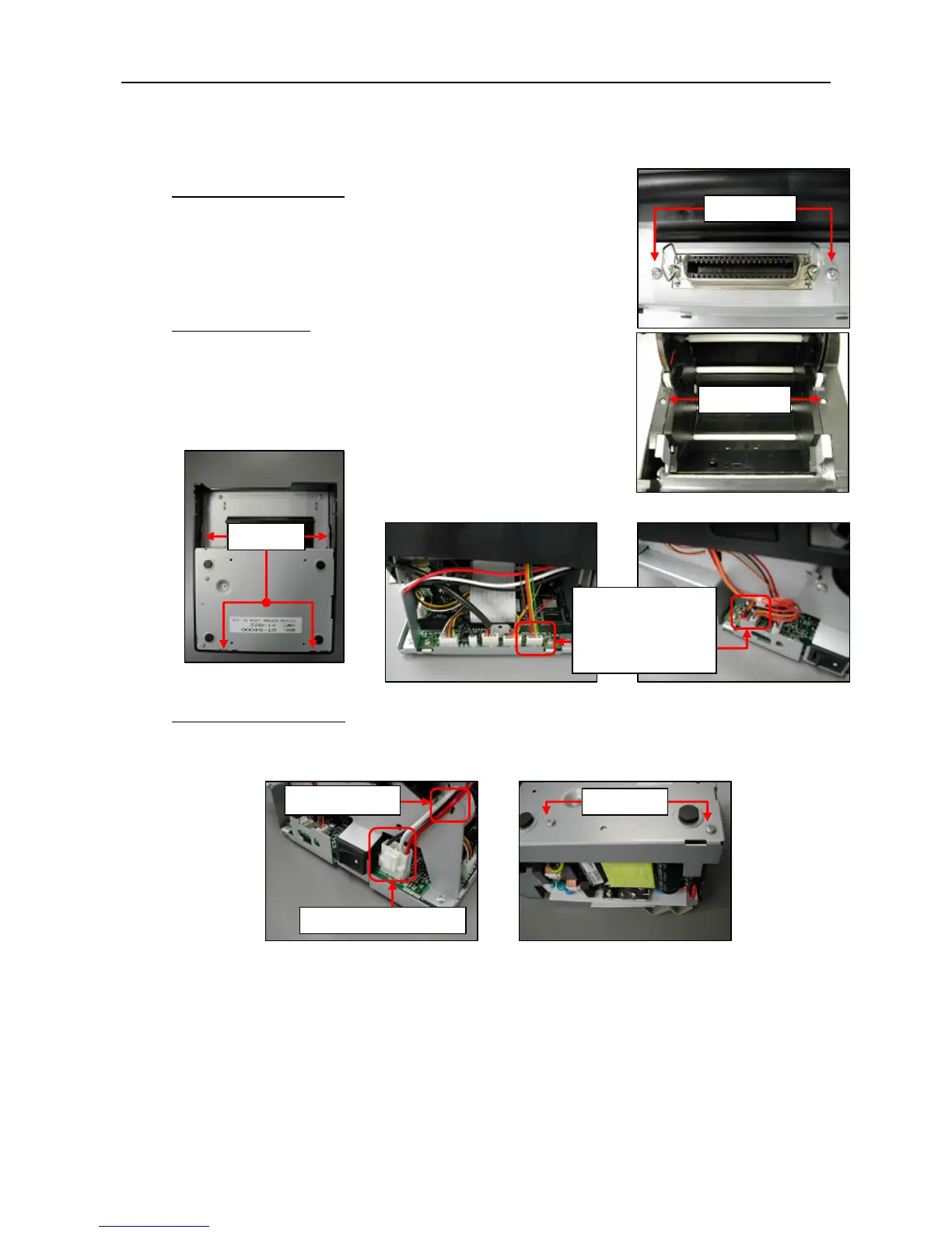
3. Removing Power Unit
・Remove the connector on UNIT MAIN PWB and remove cable from the fixed groove.
・Remove the two M3x6(ST) screws from the bottom and remove the power unit.
M3x6 (ST)
M3x6 (ST)
Hooks
M3x6 (ST)
Connector to remove
Fixed groove
Connectors to
remove:
One in left figure
Two in right figure
 Loading...