ELECTRICAL
SYSTEM
Checking the alternator output
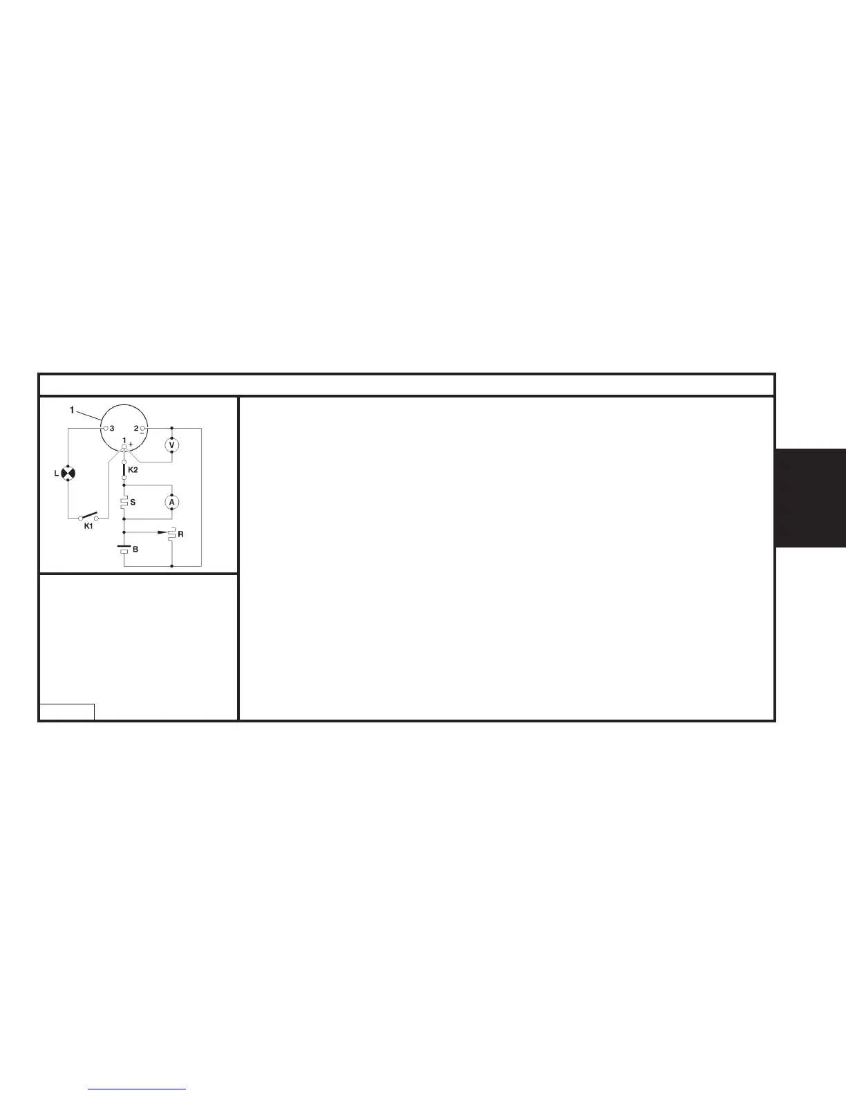
Connect as shown in the diagram opposite, using an ammeter (A), a voltmeter (V), and a rheostat (R) or
a Volt/Ammeter/Rheostat combination.
Referring to the vehicle’s equipment specification (see table opposite), adjust the engine speed and
rheostat charge to obtain U=13.5V.
Reminder : The excitation energising current will flow through the warning lamp; check that the warning
lamp comes on when the ignition is switched on. It should go out when the engine has started (accelerate
slightly).
Checking the voltage regulator
Set the rheostat to zero and disconnect all the electrical consumers.
Display 3000 alternator rpm. If U alternator is > 14.7 V, the regulator is faulty.
Note: These tests should be performed with the engine hot and the battery fully charged.
Method of reading the alternator speed
Fit a reflecting shim on the pulley of the alternator.
Adjust a stroboscope to the frequency equivalent to the control speed.
(e.g. 2000 rpm = 2000/60 = 83 Hz)
Adjust the engine speed so that the shim appears fixed.
CHARGING CIRCUIT - ALTERNATOR WITH MONO-FUNCTION REGULATOR
D1AP025C
185
A : Ammeter
B : Battery
G : Generator
L : Warning lamp
K1 and K2 : Switch
R : Electric charge
S : Shunt 200mV/200A
V : Voltmeter
1 : Alternator.